Updated 9 April 2020
Note update on motor specifications and addition of alarm and confirm buttons. This is all key safety information.
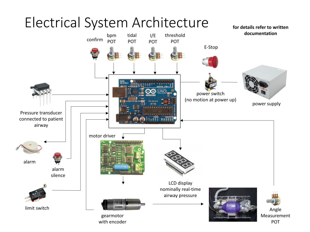
This page provides a description of the minimum hardware set required to control the ventilator as described in the other documentation.
Motor & Encoder
The mechanical system should be driven with a motor under closed loop control. For feedback measurement, we are using a DC gear motor with integrated quadrature feedback. This is the safest solution.
The beginning point for motor selection should be the Power Calculation based on the force needed to compress a bag.
Motor selection will then vary highly as a function of your geometry and we provide information on Motor Selection, based on our design.
Caution: We have investigated and do NOT recommend stepper motors. They are very hard to control when loading changes.
Power Supply
Nominally, a power supply that can deliver 12 V and 5 A is expected to work. Rapid deceleration of the motor causes supply-voltage spikes and must be avoided via correct motor motion profile design. Capacitors should be added across the H-Bridge power leads for extra protection.
An alternate power supply would be to use a car battery with a 5 A car battery charger connected. This will allow for very high instantaneous power draws and voltage spike absorption. The battery will double as a ~2-3 hour backup in case of building power loss.
Backup Power
We are recommending using an uninterruptible power supply(UPS) with a runtime up to 30 minutes. This should natively incorporate an alarm in the case of power loss. (Nominally, we source from APC / Schneider Electric.)
Controller
Currently, an Arduino Mega is used as the microcontroller in this project. This larger, more powerful Arduino is used because it has additional digital, analog, and communication channels. This allows us to incorporate more peripherals simultaneously, such as:
- a screen
- a serial port to the motor controller
- an SD card
- 3 buttons
- 4 potentiometers
- one buzzer
- one light
- one pressure sensor
- one under-voltage sensing pin.
This board is used because it has a well-established, free development toolchain, extensive online support, documentation, and community support.
In previous revisions, the microcontroller used was an Arduino Uno – readily available and easy to program, with extensive online support and documentation. It provides 6 A/D pins (for potentiometers and pressure sensors) and 13 digital I/O pins, including dedicated hardware interrupts (for encoders) and PWM pins for H-bridge driving. Eventually, when adding many peripherals, buttons, and communication ports, the Uno ran out of pins, and an Arduino Mega was used instead. Other industry validated controllers can be used, and we may implement them in the future.
Motor Driver
Use any motor driver with sufficient voltage and current ratings to meet the motor power specifications. Closed loop servo controllers can also be employed. Our control strategy is PWM with a H Bridge. For fastest implementation using cheap, off-the-shelf parts, we recommend an Arduino compatible motor shield. More industrial versions will be safer. Main recommended motor controller specifications:
- Speed plus position command input that is robust
- Accepts quadrature encoder input for closed loop feedback
- Has integaretd safety features, including but not limited to, temperature sensing and current limiting that can be communicated to the controller. (What action a fault condition should initiate is not yet defined, ideally this will throw an alarm and message.)
- Capable of handling up to 15 A. (This is to handle random spikes; you must conduct testing to determine your requirement.)
Caution: Motor controllers can create significant heat inside an electronics enclosure, be sure to consider cooling. Solutions include active cooling with a fan, connection to a protruding heat sink or connection to a large metal chassis.
For reference, we are using a RoboClaw Solo motor controller to control a brushed DC gear motor. The RoboClaw firmware uses a velocity PID controller and a position PID controller to command the motor to a desired position at a desired velocity. The PID values must be tuned in advance. Other motor controllers with similar functions will work, we do not recommend any specific controller.
Inputs
Pressure sensor – Receives a voltage proportional to the pressure in the patient’s lungs. Used to determine max pressure reached during inspiration, and to trigger when the patient is attempting to breathe in during assist mode. Minimum pressure sensor selection:
- Differential (to sense negative pressures)
- Range of up to 100 cm H2O. This is a 2x safety factor.
- Accuracy on the order of 0.5 cm H2O
Note on Plumbing: The pressure sensor must be connected to the Ambu bag’s sensing port or somewhere in the airflow, as close as possible to the patient, past any valves.
Control knob potentiometers (POTs) should all be single turn, 10 KΩ. Single turn is to allow for specific settings to be marked on the face plate.
POT 1 – Varies inspired volume, sets angular oscillation of the arms. During operation, each arm varies by a maximum of approximately 20°, corresponding to fully squeezing a large bag. This dial varies position from 0% (fully open) to 100% (fully compressed).
POT 2 – Varies the BPM. This sets the rate from 0 to the maximum BPM given in the clinical document.
POT 3 – Varies the I:E ratio. Range as given in the clinical document.
Note: It is not essential that this be settable, one value greater than 1:1 can be selected and the POT repurposed as a threshold for over pressure. (Multiple clinicians have indicated that varying I:E is not critical.)
POT 4 – Sets the pressure threshold for detecting assist control. This varies as described in the clinical document.
Switch – Power on / off
E-stop – Instantly deactivates the system. This can be the main power switch, but a single pish must fully depower the system. This will allow the bag to be removed and immediate conversion to manual bagging in the case of any major failure.
Toggle Switch – Mode selection from volume to assist control.
Momentary Button 1 – Used to temporarily silence alarms. This must be debounced.
Momentary Button 1 – Used to confirm a change to one of the POTs. This is a necessary safety feature. This must be debounced.
Limit Switch – Used for homing the arms positions.
Output
LCD screen displays airway pressure in cm H2O. Other functions can be incorporated later. We are using a 20×4 character LCD display as this will display the minimum information, described in under interface. Any display better than this will be sufficient.
Audible alert buzzer will identify multiple fault conditions.

Recent Comments