Updated 28 March 2020
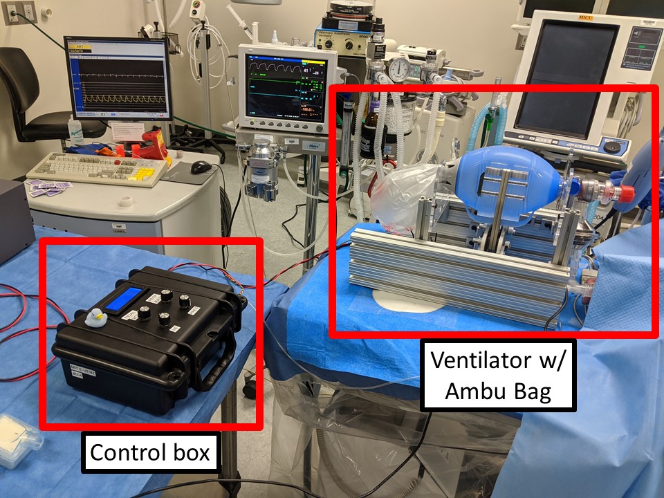
This page describes the operation of the MIT Emergency Ventilator Units 002. (Three units of the same design exist.) This is our best attempt to provide a minimally viable control system with wide applicability globally. Groups may want to add additional layers of safeties. This is just a guide.
Note: While the mechanical hardware design is changing rapidly and some of the underlying electronics are being upgraded for prototype purposes. the operating principles are relatively design frozen.
Scenario
The system will initially be setup by a clinician explicitly skilled in respiratory management. The parameters must be tuned and the patient monitored carefully. Once stable, they can be left in the care of a clinician not skilled in respiratory management. In the case of any change in patient condition or an alarm, the system must again be tuned by a skilled clinician. In the case of any serious concern, the bag can be manually removed from the machine and squeezed by hand until the fault is addressed.
Operation
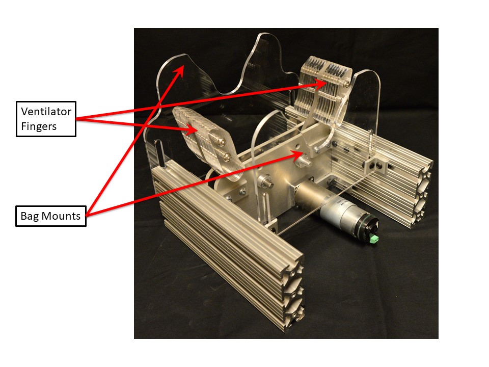
- Gently open the fingers by hand if not already open. This takes some force, but it is safe.
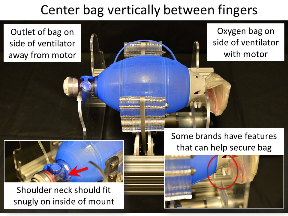
- Position the Ambu Bag in the cradle between the fingers, following the directions given in Figure 6.
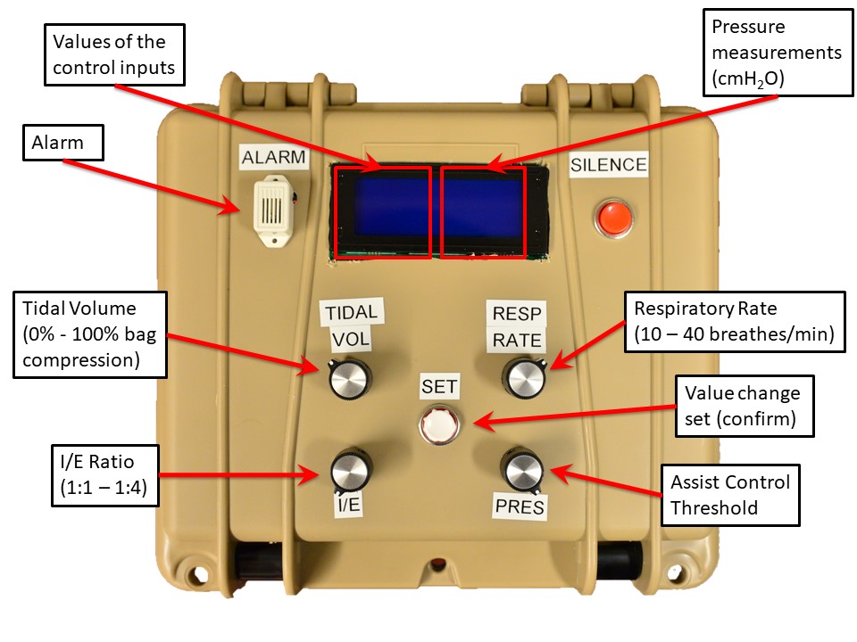
- Ensure that all dials shown in Figure 2 are turned counter clockwise to the lowest position.
- Check that nothing is in the way of the fingers.
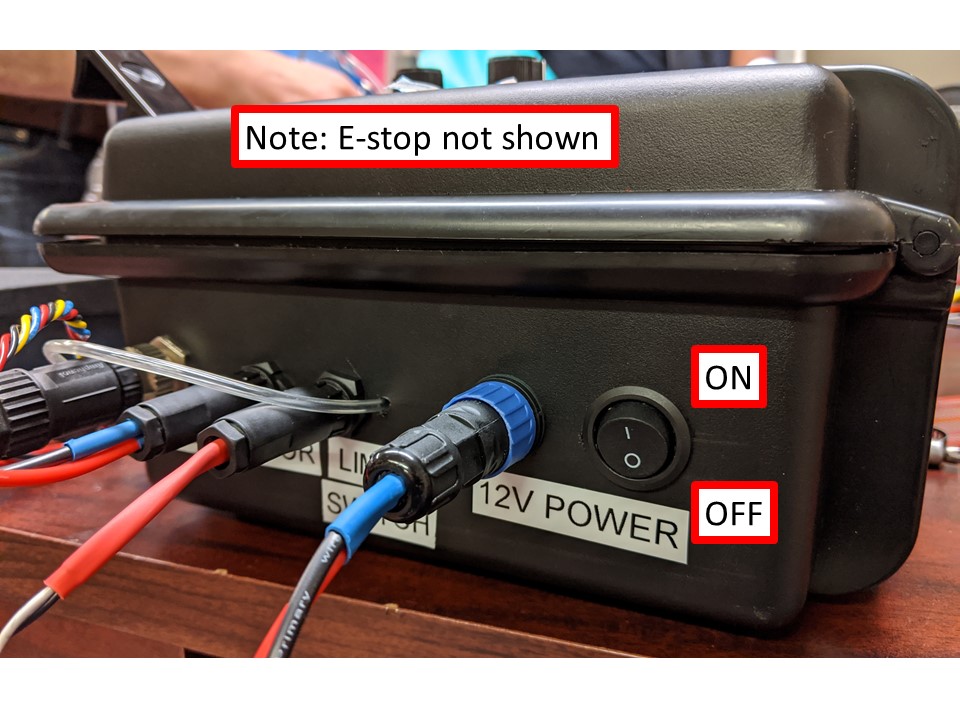
- Power up the system. The system will start moving immediately and home to the fully open position. Then it will slowly move to the edge of the bag. (This position is hard coded; it could be settable in a more sophisticated version.)
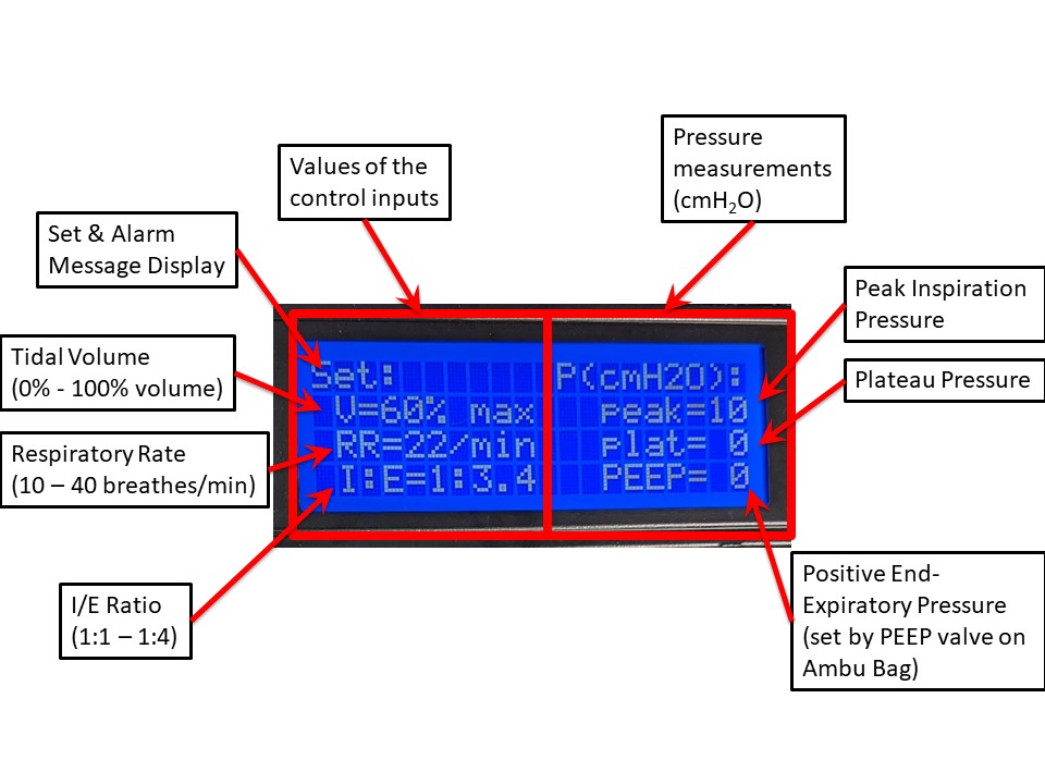
- Set the desired Respiratory Rate, Tidal Volume and I:E knobs, as shown in Figure 2, and confirm the values on the display, shown in Figure 3. Press the Set button to apply.
- Increase the Tidal Volume to a low setting (as determined by clinician) and press the Set button to apply. The system will start pumping. Confirm correct operation.
- Once the machine is confirmed pumping, connect to patient and increase the Tidal Volume to the desired larger value and press the Set button.
- Monitor the peak and plateau pressures and adjust parameters as per clinical guidance. PEEP pressure should be observed to match the setting on the PEEP valve.
- Do not leave the patient unattended.
- Monitor vital signs, listen for alarms and respond.
- If Assist Control mode is desired, increase the Threshold knob and press the Set button to apply. This will increase the setpoint with respect to the PEEP.
- Respiratory Rate should beset to less than the expected patient respiratory rate, i.e. the machine waits longer than the patient would.
Note: Spinning potentiometers (POTs) will cause the display valued to change, but will not change machine behavior until the Set button is pressed. If the Set button is not pressed within 5 seconds to apply the new settings system will alarm.
Caution: If a POT is changed, but Set is not pressed, a potentially confusing situation will arise whereby the machine is different from knob settings. Potential solutions better than the alarm include: 1. Shielding the potentiometers to prevent accidental turning. 2. Using a potentiometer that must be pulled out to set. 3. A rotary encoder with a pushbutton; this will allow the button to be activated, set and deactivated. More sophisticated hardware and software solutions can be implemented.
Alarms
In the case of an alarm, the system should attempt to maintain operation. The Silence button will temporarily pause the alarm for 1 minute. Alarm conditions are checked for once per cycle. Details are provided on the Alarms page.

Recent Comments