Updated 28 April 2020
By downloading material I agree and acknowledge that I have read and agree to the Terms of Use.
Prototype Code
This code is provided for reference use only. Our goal is to help others understand the function of our Version 3 prototype system, with regards to: delivering tidal volumes, breaths per minute and I:E ratios; visible and audible alarm functions; and the display operation. Assist control, to detect patient breathing, is implemented, but is still a work in progress. (Synchronizing with a human is non-trivial.) These features are only a baseline and others will likely wish to add more safeties and features. Our code is specific to an Arduino Mega, RoboClaw and DC motor. Our code is NOT approved by any regulatory body to operate a medical device.
Caution: Any group working to develop ventilation or other medical device must conduct significant hardware and software validation and testing to identify and mitigate fault conditions. This is essential to ensure patient safety.
Access the code from GitHub
https://github.com/mit-drl/e-vent
Please note the Terms of Use and that we do not have the human resources to provide technical support.
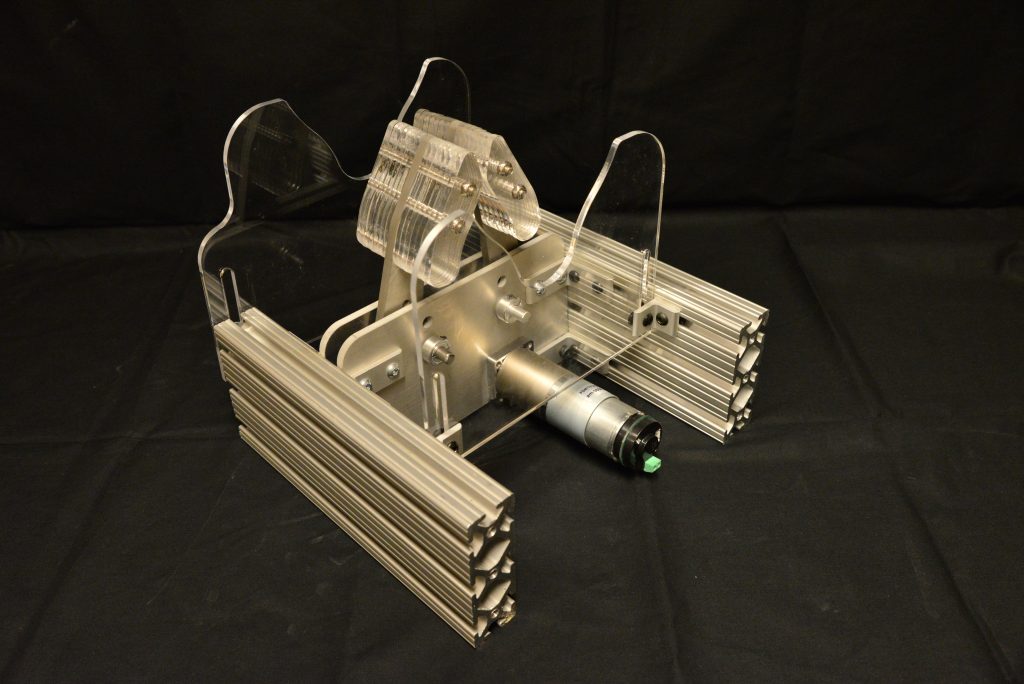
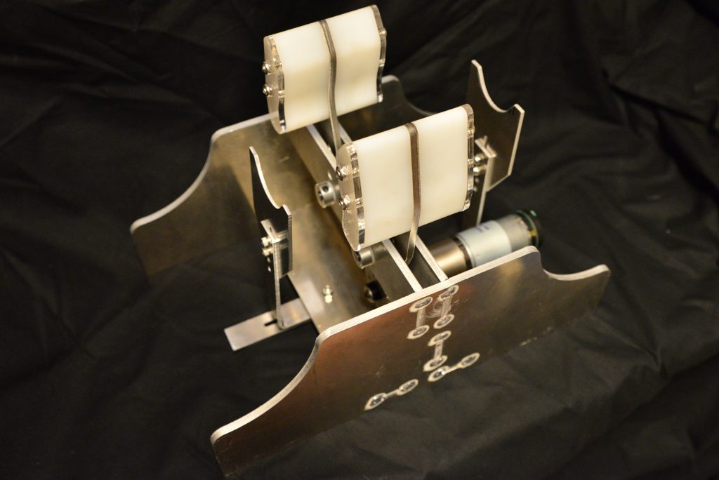
Version 3.1 – Hardware
Version 3.1 is shown below.


Source files for mechanical design:
- CAD files: Zip file (with help from Neal Drapeau)
- Mechanical BOM: Spreadsheet
Two design tools that will allow you to explore different gear configurations and select appropriate motors:
- Gear Stress Estimator Spreadsheet – This is designed to calculate the maximum bending stress experienced by gear teeth. This should be compared to stress – fatigue curves for a given candidate material.
- Gear Torque and Speed Estimator Spreadsheet – Purpose: This outputs the torque and speed required by the driven arm and the pinion. The radial load from the pinion on the gearbox shaft is also calculated. The speed and torque results should help you select and appropriate motor, based on comparing these to a given motor’s curves.
Source files for circuit diagram:
- KiCad project: Source files, Gerber files
- Electrical BOM: Spreadsheet
Past Designs
More details are available in Past Designs.
Version 002 (T-Slot Aluminium)
Download CAD file made by Neal Drapeau
Version 002 (welded)
Note: The shafts on the gear-driven fingers need to be keyed. This detail is missing from the CAD below. We’re in the process of updating our designs; an improved model will be shared here soon.

Hello,
Do you have any blueprints available?
Thanks
Hi, We are looking to mass produce it to save hundreds of thousands of lives.
We (SolarSCADA) are working on a prototype hardware device to control these (and the MUR-type equipment).. I’m making it as close to common-jellybean components as possible. We’ll include motor drives for Stepper and Brushed DC w/ Feedback, plus analog outputs for the MUR-Type equipment that uses proportional valves. This will also be able to drive the AVE-Inspired ‘Tubes and industrial doodad’ solution. I’m looking for an STM32 or PIC C developer to help; I do both, but given the time schedule we have, I don’t have time to do this myself. I’m an EE and PCB guy, who does software as a secondary effort. Reach out to me- glinder@solarscada.com if you’re interested in getting a “can be assembled anywhere in the world with a flame-heated soldering iron using jellybean parts” type controller for these devices..
Just giving another update here- Schematic layout is going well. Hopefully will have schematics done Tomorrow, with PCB layout done Wednesday. I’ll be updating the Community here with drawings and such of the V1 prototype controllers. Once these are done, I’ll ship one to my Software Team who will whip up some code based on the specs here. I’ll also release a data sheet / basic instruction manual for installing this PCB in the prototype hardware. We’re going with an Overly Beefy motordrive on the prototype, so we can drive Whatever Motors anyone finds, made from fairly standard parts available worldwide.
Please help with dwg specifications or parts step files,Mexico will much appreciate your help, people will need one ventilator for each family, Mexico death rate is above 28% till now, collaboration will bring hope
https://gisanddata.maps.arcgis.com/apps/opsdashboard/index.html#/bda7594740fd40299423467b48e9ecf6
You probably mean 2.45% Death Rate.
Our Schematics are just about done. Just need to finish motor drive section, and will begin layout tomorrow. I’m about a day behind where I wanted to be, but, well, we’re going good over here.
Features:
(1) Big Motor Drive based on standard Reference design (12 or 24VDC motors up to 30A possible)
(2) Standard Pots for input (in multiple footprints, in case we have shortages)
(3) Screw Terminals for Power in and Motor Out
(4) Sensorless Feedback: No need for Motor Encoders, as we can measure the position of the grippers directly.
(5) Low cost display module talking via I2C
(6) Small Footprint- Will probably be around 6″ square or so- We have lots of extra space so we can place multiple sizes/shapes of the same style of components to not have to relay the PCB.
(7) Low cost: Not exactly sure yet on Finished Cost, but right now, I’m guessing the finished control boards will be less than $100, including the features above.
(8) ATMega based design, so you can pull the 28-PDIP off the Arduino and slap it into our board if you need to. We also support the SMT mount package for assembly line production.
Hello Greg, not to take too much of your time as the team is hard at work. I take it you will be releasing the total drawing package; the final prototype mechanical gripper design with cad (not sure V02?), complete electrical architecture/schematic with BOM used in the prototype, motor control (DC or stepper – just saw you note above about doing away with feedback encoder and just using gripper limit switches, angle sensor, etc.) and the Arduino source code if that’s whats used in the proto. A complete PCB with ATMega would be nice but we wanted to build few prototypes so we can test it in a clinical setting in collaboration a target hospital in mind. The for all the hard work you guys putting in. Any feedback from other members is appreciated.
Hey Jawed:
I’m not part of the MIT Team– I’m just another dude rolling a board to solve availability problems and get things going. As soon as I have code and a board schematic and layout complete, I’ll be releasing this to the Wild as such for people to build it in. The MIT project uses Arduino, but so far I don’t think I’ve seen code released for it yet. I’ve got a team doing code for ATMega natively, which we will also be releasing seen. I’m just posting updates here as a service to the community.
Thanks Greg! 🙂 everybody and their uncles are contributing to this cause, do little challenging to keep track of who’s doing what. I take it, your concentration is on the PCB with ATMega? and if I understand you, are you planning on porting the MIT Arduino code (or developing your own) to run on the ATMega platform? How about the motor driver control interface, plan to use what MIT puts out? or any possibility of simplified stepper motor support without encoder and just using home limit switch to home it on every cycle? with relatively low speed to squeeze the bag and without any significant inertia, I don’t see the stepper overshooting too many steps if any. And it would not propagate if it’s homed on every cycle. Anyways, just a thought. Thanks again!
Heya-
Yeah. I’m designing a Control PCB with the ATMega. If MIT ever shares code, yeah, I’ll port it, but if they don’t, we’ve already got some software guys working on this.
The Motor Driver interface we use is PWM to the Driver, with current feedback as analog, and overload alarms as discrete. Assuming that the MIT Code is reasonably well written, re-writing the PWM code that they use and replacing it with our encoderless code and PWM interface style would be pretty straight forward.
I was thinking of Stepper Motors too- I’ve done lots of stepper stuff using L6470 integrated drivers, which would probably work Great for This. But I had to start Somewhere. I agree with your opinions on that, and I really doubt that steppers would miss that many steps in this application, unless the power was lost or the gripper-grabber hands were forced manually.
However, I’m just One Guy working on cranking out something urgently.. If we get software going on this PCB, Rev 2 will add some more stuff- Including I2C and SPI pressure sensors, plus maybe the stepper output.
Hey – Just a minor suggestion – going from ATMega to MK20 or MK22 from NXP gives you much better resources and capabilities – memory , float point calculations, timers etc’. and you can keep the sweet simplicity of Arduino language using the teensyduino from PJRC. just let out the JTAG pins so you can upload code and you have a really impressive M4 MCU for about 2$.
I’ve done it several times and highly recommend it.
https://www.pjrc.com/teensy/
@Greg Linder, We are also trying to make a mechanical ventilator in Bangladesh. It will be highly appreciable if you kindly share the source codes with circuit design.
If you ever have the opportunity, please share your project at the following mail:
mohammad.nasim046@gmail.com
Hi Greg,
Great initiative by MIT team, great effort from your side then.
I`m from Tanzania, working with Dragger Family Machines. I`m so interested with the design and i need to implement it in the eariest .
As is my interest to implement it, can you mail me the design schematics and the code used?
i will be waiting for the feedback from you.
Thanks
nako.kidindima@gmail.com
Thanks again for your effort
Thank you very much Greg. We urgently await your great contribution.
Dear:
Here in Honduras we are working to have this prototype up and running, and we would like to know is there is an Arduino code already or it has to be done ???
please share the arduino code on the email mariaali.3110@ieee.org as i am trying to implement this design with my fellows. Thanks in advance
Hi. where can i get the arduino code for this MV?
Dear Maria,
If you find any code, please share it. As i am also following this project.
Regards.
Ali Nisar
Email: alinisar01@hotmail.com
Hello, if you find arduino code, share to antoniocordovalaguna@gmail.com If I find it, I will share you. Thank you.
Hello,
Any luck with the arduino code? Please share with me as well if received.
Regards. kolajoadewumi@gmail.com
Hi Hello did you received the code?… Please share it to me too… tony.deleonv@gmail.com
Thanks
Hello there here in Nicaragua I can’t find an arduino, somebody knows if we can make this control board using a 555 timer control?
Hello, I am Alfred from Botswana. Already done fabricating the mechanical design. Moving to the controls system now. Please if you find arduino code, share to akpone88@gmail.com.
Dear Alfred.
I am Victor from Chile, I am interested as you are in the manufacture of Mechanical Fan, please share the plans for manufacturing, for your contribution thank you very much
Victor Adriazola R.
Howdy, Greg. I work for a university located in Pennsylvania. We are looking to get into producing ventilators for our local health care providers. Your board design sounds promising. When your design is complete, do you plan on posting links in this thread? Or is there a website you have set up specifically for updates on your piece of this project? Thanks! Looking forward to seeing the fruits of your, and everyone else’s, labor.
Hey Matt:
Yeah.. I’ll post links on this as soon as I get to a stage that’s reasonably postable. As others have mentioned in this thread, some code would be Nice. I can’t get our Code Team running here (really) until they get this hardware in-hand, which will be mid-next week at the earliest. I’m also emailing with several people about just making a Stack of these PCBs, and sending them out to everyone who has the capability of making mechanical contrivances with motors. We’re also working on a website for stuff, but, well.. all these things takes time. Once I get the PCBs sent out for Fab, I may have a day or so to set up even more collaboration tools. But yeah, all the stuff I’m making will be publically release here, possily hosted on my business’ website (www.solarscada.com) if I have time to update that.
Hi Greg,
Great initiative by MIT team, great effort from your side also.
I have a company into high precision devices, electronics and embedded software
If you can mail me the design and schematics, I can get the code done at the earliest
Thanks again for your effort
N.kashyap (n.kashyap@midas.in)
Thank you. I would be interested in the code as soon as possible.
Hi, Greg.
I have a good experience on the drawing software I teach at Ets in Canada.
If I can help you make some plans I would be honoured.
Mathieu.
I’m interested. I’m CEO of a beverage company with 3 factories across the US. Electrical Engineer by training and I think that my maintenance mechanics and electricians are capable of doing this, I certainly am and I have LOTS of interest.
Greetings, all: Here’s update for 4/3/2020 on our Universal Bag Pumper PCB Controller.
(1) I’m on Layout now. Several people sent back great suggestions and caught some errors in the schematics I sent out. I ordered parts today for the first round protos, and depending on how much concentration I have, I’ll be sending parts out for Fab tomorrow, which should arrive on Monday. I hope. Then, I’ll solder these up, and send them to folks who offered to help with Software, and get that Code Going.
MIT People, if you have Arduino code that works, it’d Be Swell if you could share that with me or the team I’ve put together. I’m using ATMega 328, so we can put whatever you’ve got in our PCB with (hopefully) minimal changes to device pinning choices and whatever else.
(2) The design is Super Simple- BOM Cost is probably~100 in 1k unit quantities. I’ve already sent off the pre-release BOM and Schematics to several people for review and pricing. As implemented, this controller implements the following
(A) ATMega 328 in both SMT and PDIP packages.
(B) High Current Motor Driver based on a TI Reference Design (up to 30A @ 24VDC. I really hope nobody uses that, as that’s a lotta wattage for this)
(C) (5) POT inputs for Tidal Volume, Resp Rate, I/E Ratio, Assist Detec, and “AUX” for something that I missed.
(D) (4) Pushbuttons for START, STOP, ALERT SILENCE, and an Extra, for What I missed.
(E) Headers for all controls so you can mount your pots and attach a bigger buzzer to the alert output.
(F) 3V3 power supply for CPU and inputs, 3v3 or 5V0 for pressure sensors
(G) Multiple footprints for multiple packaged pressure sensors from Honeywell and NXP
(H) (2) connectors for daughter boards that get attached to grippers for accelerometer-based position feedback. I’m designing those next.
(I) (1) connector for a display that talks I2C.. We’ve got lots options here.
(J) The whole PCB is about 9″ x 7″ currently.. Most of that is space for the labels and adjustment pots.
(K) Screw and Spade Terminals for Power Supply and Motor Output
Will post again once I get PCB artwork finished.
Hi Greg,
Thanks a lot for the coordination you’re making in this project. I appreciate your summaries and follow up. I did download a number of files but am not sure if I have everything that was posted so far, because the files are in different locations in this forum’s timeline. Can you please put all the files in one single location so we can check if we got everything needed, Thank you very much.
Greg,
Greg , I’m new to that thread !
Did you put an external watchdog to reset the MCU if SW hookup? That should trig the alarm (Buzzer and LED status too
Thanks for the effort and commitment !!
Carl
Greg and ALL,
THANK YOU ALL for your help and efforts. I can help with:
1) Test protocols (Design, Writing or Review)
2) Failure Mode Root Cause Analysis
3) Specification, Drawing or Documentation control activities
How can I help anyone?
Best,
Do you have Arduino code for this specific project.
Can you please forward it into prajod@navgathi.com
Greetings, all:
Sadly, I missed the PCB Fab Cutoff today to get boards by Monday. I’m about 2 days behind what I set out to do, but, well I’m still going. I’m almost done with Layout, and will be sending out everything again soon.
Some updates on the PCB:
MIT: IF YOU GET ME A PINOUT OF YOUR ARDUINO THAT INCLUDES ALL YOUR PARTS, DISPLAY, AND P/N I CAN ADD IT TO THE PCB AND GET YOU PROTOTYPE PCBS BY THURSDAY THIS COMING WEEK. The information you posted doesn’t allow sufficient information to roll a PCB for your particular implementation.
The board will be around 9.5″ wide by 6″, with buttons along one long side and connectors on both short sides. Mostly this is to accommodate the frankly ludicrous amount of footprints and stuff for multiple POTs and Pressure Sensors, the huge connectors for off-board plugs for stuff that may need interfacing (with silk-screened labels for pins and stuff), and the Giant PCB Heat Sink you need for an integrated driver capable of swinging 20A worth of DC to drive the apparent Leaf Blower Sized Motors that apparently this application may need. I also have room to mount a Full Arduino (whatever) IF MIT RELEASES SOMETHING THAT SHOWS HOW THEIR CODE USES THE IO TO TALK TO TO THEIR POTS AND BUTTONS, but well, if I don’t know how they plan their code to use this, then I can’t route this. If you read this, could someone please email me about this? I’d like to support your endeavor with real hardware we can start testing and stuff, but, well, I can’t if you don’t release anything to help us out here.
That all being said, we’re still rollin’ along here. Regardless of the MIT Team’s code progress, this PCB will have the (2) ATMega328 footprints with their crystal or Resonator (under the vain hope that MIT Releases Some Kind of Code Soon), The Motor Drive (based on the TI DRV8701) and now also the BLUE PILL STM32F103 dev kit thing.
I’ve already ordered parts, and hopefully will get the first few units in the folks who asked for prototypes for software dev next week. I’ll also be putting the design on Github for those who want it, and maybe even spin up a Kickstarter for PCB stuffing so we can get some cash moving around here to buy parts and things for a Big Run. The boards will include all SMT Parts, and whatever pots and connectors I think we need. I’m thinking (2) versions. One with sockets that will take either your ‘328 or the Blue Pill, and the other with the ‘328 SMT stuffed. Can’t get assembly quotes until PCB layout is done, so, well, here we are.
Everyone who has emailed me will get a link to the Github for this as soon as it’s released, and I hope that Code Implementing the stuff here will flow forth with strength and vigor.
There’s no separate watchdog chip.. This is Very Bare Bones, as I’m trying to keep the cost as Cheap as Possible and the BOM list as easy as possible to make it easier to fab quickly in fairly vast numbers. Maybe in Rev 2 I can add that.
At the very last, in the last week I’ve been a pretty solid expert on just exactly what a ventilator is and how you use one, so I guess that’s a nice new skill to add to my pile of stuff.
Hello,
Thank you for your efforts. I would appreciate any code if you have it. Stay Safe
ty
mackenzieelectric@gmail.com
Greg – I work for a PCB manufacturer in Texas. We may be able to turn boards around for you in the same day. We are still up and running due to our defense and medical business and have plenty of raw materials. Capacity is tight, but we could work these in. I’d also like to get a copy of the current code. You can contact me at bradyhurst@netviagroup.com.
@Greg Linder
Thank you. It will be very helpful for people like us who have zero ability to buy a professional ventilator or get in hand. I am no expert, I know I can not help you with anything. But if you succeed to make it, and make it open source I would love to try to make as many as possible for the locals.
my email address engmoseur@gmail.com . If possible, please notify me and give me all the design, diagram, schematic, and codes which I need to make it.
Thank you once again for the work you have done and you will.
Hello.. Can you send me the arduino code ? My e-mail: imsunny3229@gmail.com
Do you have resources, funding, etc to mass produce this equipment in this way?
Thank you Greg,
May I have your email address please? I might be able to help you with funding. You can reach me at halha014@fiu.edu
Thank you,
Hi, we can do something about this, but after the project is basically accurate, we need to give directions
In addition to the mechanical part, 3Dprint can be considered, which is conducive to distributed production in the future
In my area, we lots of machine shops, with cnc controls, please let me know as soon the protype is ready.
thank you for sharing file. May I have nore detail drawing from cam mechanisiom?
Hi!
I’m Brazilian, and i’m working in a O2 reator. The principe of my project is give to patient a atmosphere richier in O2 in order to compensate the lower volume of air breathed and the loss of eficiency of the lungs.
I’m Very excited, because this thing os working, and now i,m trying to upgrade both projects (my reator and MIT E-vent) unifying both in a single project.
Anybody could work with me? I’m Environmental Engineer and i began to work with Arduino, IoT, DIY and basic electronic just 2 years ago, so, i’m still very limitaded, i have a lot of viable ideias that i haven’t the knowledge to turn it in a functional device…
I would love to be part of a study group and project execution. A huge group of Makers can solve anything!
i work at a company very capable of making these, i downloaded the mechanical file into solidworks and got this error, can you help?
“the drive motor is missing” email is Charles.monjak@kla.com
thank you for the great work
search in grabcad.com, bridge H motor control
Hi everyone
I want to know if blue prints are available too. Until we know, you can open the CAD file for either unit in CAD software(I use Fusion 360) and use a measurement function(in Fusion 360 it is under Tools>Inspect) to take measurements.
Bumping this. Please help.
Does anyone know the status of ARDUINO CODE ? Has anybody been able to get this?
I am working with a group of Afghan women who are trying to build this ventilator. They have a prototype built but need to work on the pressure sensors and control loop.
If you could help us, with code and board fabrication, for example, could you please email me at: Doug@TripleChin.org
We are desparately in need or ventilators for this country of 38 million and fewer than 300 working ventilators…
not yet
Repo we can inspect? Don’t want for it to be perfect, many eyes.
Hi, We are looking to mass produce it to save hundreds of thousands of lives. I am trying to set up a collaboration with the government of maharashtra, India. I have 25 years experience with medical devices. Please help.
How can we support your efforts there?
kindly send ardiuno code
Hi Mohsina, can you send me arduino code to ingenieria@marlabrador.com ? I´ll be grateful to get more info and contact you for this product development. I´m working in PTC CREO, so, I can send you plans and drawings.
Thanks
Hi Mohsina, can you send me please arduino code to b.o.arturo.developer@gmail.com? We are trying to develop a team at the national institute of astrophysics, optics and electronics in mexico to help our people with these teams. We would appreciate your help.
Sir if u got arduino code please send me on my mail id jitendrapatil56@gmail.com
kindly send me code if u got. they released.
Masum,
The code has been release about two days back. See the download tab at the e-vent website.
1) Please write a phone number we can reach you at. You can email it to me directly.
2) Design files, software code – full, to be able to have 10 working prototypes working ASAP to prove concept.
3) Not sure if you saw the Migrant workers exodus issue in India recently, Covid 19 is about to get out of control in India… we need to act fast.
4) I am getting a team ready, but we won’t find top medical device talent here. So if your guys can advise our team, that would help tremendously.
Hi Mr. Kaushik, I’m from mumbai, India also trying to develop the ventilator for the most probable future tragedy. It will be mutually benifitial for us and the country if we colaborate. My mail id is pravintpalve@gmail.com and contact number is 8422075895. I’m expecting a reply from you.
Hello there, pleased to meet you…
I’m from Honduras, we are desperately worried about this problem on my country and worldwide… Me and a team wanted to produce this solution to bring it to the hospitals here, because we have a very poor medical support and people are dying because of COVID-19. I work on a sugar mill plant called Compañia Azucarera Tres Valles, and the CEO Mateo Yibrin asked me about build the E-Vent to help our health sector here in Honduras.
We will very thankfull if you help us, sincerely.
jaflores@tresvalles.hn
+50497996217
Dear Kaushik Lodh
I’m from HaNoi, Viet Nam. Please, send me the arduino code. My mail id is mgtuan@gmail.com. Thanks you very much.
same here please
marc.said@etaexperts.com
+201206631657
please share the arduino code on the email mariaali.3110@ieee.org as i am trying to implement this design with my fellows. Thanks in advance
We are based in Mumbai and interested in the RnD for a prototype suited for mass production in India. We would like to be a part of your team.
Email us at info@biokitindia.com
or Whatsapp 9769492092
Hello Kaushik Sir, myself Purva Durugkar a student of Biomedical Engineering , being a Biomedical engineer iI’m also working on similar kind of project would be highly obliged if you make me a part of you’re team as it help me enhance my skillset.
Here is my email; purvadurugkar22@gmail.com
contact no; 8652188488
Thank you, waiting for you’re reply sir.
Hello Mr. Kaushik, Purva and astish …..
This ia pravin Dhebade …..propriotor of Vaishali Automation and Robotic Technologies based in Pune , Maharashtra.
Sience I am in Automation ….we can combinly develop the said ventilator with the help of E. Vent. MIT
My contact Number is 9689938951…….
is that a right source for info sreeram.mohan@altair.com
Please Be In touch
sofienmessi123@gmail.com please send me the arduino code!!
Dear Kaushik Lodh
can you send me arduino code to rone29504@gmail.com please.
Thank you so much, waiting for you’re reply sir.
I have created a different design that can be improved with the great knowledge base in this website. My working prototype can be seen here.
https://devpost.com/software/ventilators
https://youtu.be/4oB0j6TyGx4
I am originally from Mumbai and I am planning to work with my brother-in-law there to see if this design can help others. We would love to collaborate. He can be contacted at ranjitp@gmail.com.
I can be reached at sudhir.iit75@gmail.com
Hi Kaushik,
We are looking to help produce low cost ventilators for India too.
Please contact sreeram.mohan@altair.com to discuss coordinating efforts.
Regards,
Pete
Hi Everyone. Is there a hardware / equipment list available. I would like to start procuring local parts in Toronto, Canada in hopes that when it all arrives that your great work will be completed, and perhaps I can find a warehouse and group of skilled volunteers to assemble units for our hospitals. If such a list exists please email it to me kindly: michael.arbus@gmail.com
Good luck team!
Hey Michael, Did you find any list?
Hi Michael,
Did you find these lists? Could you email them to me? mclegg@grupofox.com We want to build these in our plant in order to donate them to our regional hospitals
isao_peiro@hotmail.com, please, can you send me arduino code full. Thanks.
please share the arduino code on the email mariaali.3110@ieee.org as i am trying to implement this design with my fellows. Thanks in advance
Hi Mohsina, can you send me arduino code to yafetsolomontt@gmail.com
Hi, Solomon can you please share the code, I will be very much grateful to you.
deepak.iiitnr@gmail.com
Dears
we can support on semiconductor components from various brands viz NXP,ST,VISHAY,Micron etc and OLED displays
Regards
Sidharth Mittal
sidhartha17@gmail.com
Hardware distributor in UK and Ireland here. I will reach out to all contract manufacturers we currently deal with. A full hardware BOM once available will be a massive help. I will make sure all components are available at cost to those that need them, taking advantage of all discounts of scale from manufacturers and will seek emergency discounts from source.
+1 on the hardware BOM. Having the right set of common parts to build & run tests with would be invaluable
+1 for the BOM. Would be nice to have the materials ready for when code and other reference documents are released.
is the code for the arduino available?
Yes, where is it?
where is it?
Hello, if they responded or if you get the source code please tell us what is the procedure to get this copy of code and documentation Thank you.
+1 for Arduino code, has it been posted?
+1
Good evening my name is Christian Farfan. You can send me the code in Arduino. I am from Jujuy Argentina, my email is cristian.jujuy@icloud.com. Mobile +54 388 4151826
Hi, where is the arduino code?
I am interested in building this. Where can one get info on how to build this?
Hello , we are interested in building the ventilator, how is the process to see the information?
hi Team,
Mohit Here ,
We are interested in building this ventilator, can you provide the details regarding electronics stuff.
In Paris, France, we are working on the MUR-Project :
https://github.com/LeClubSandwichStudio/MUR/blob/master/V0/documents/MUR_V0_GeneralFeaturesSchema.pdf
Thanks for the link.
Thanks!
Gracias Cristina. Saludos desde Argentina
thanks, greetings from Mexico.
Osvaldo
Veo que has avanzado un poco en este proyecto, comompodemos ayudar?
Cuento con un control numerico, fresa
Plantas de soldar y capcidad para producir piezas de fibra de vidrio en cantidad considerable
Sauldos
Osvaldo
Veo que has avanzado un poco en este proyecto, comompodemos ayudar?
Cuento con un control numerico, fresa
Plantas de soldar y capcidad para producir piezas de fibra de vidrio en cantidad considerable
Saludos
Gracias Christian, Saludos desde Chile.
Eduardo
Hola Eduardo. Junto a un grupo trabajando en esto. Donde estas ubicado? Has avanzado en la fabricación del ventilador? Coordinemos esfuerzos! Saludos desde Valparaíso.
Eduardo. Gonzalo. Lograron fabricar el prototipo. Saludos de Santiago
Coordinemos esfuerzos, indiquen sus teléfonos o correos. El mio es pmqueirolo@uc.cl / +56 9 92793053
x acá en Santiago
+56 9 87432347, Greetings from Providencia, Santiago ;; emaureir at gmail.com
+56 9 96911102 – manuelhernandezp at gmail.com – Providencia, Chile
Hola
feliz de poder aportar.
Yo podría fabricar la estructura (soporte) de aluminio para todo el sistema
mi cel +56 9 62181709, mi mail cristian@klammer.cl
saludos de Stgo
Hola, yo tengo todo para fabricarlo, mesas laser de alta definicion, brazos con mill KUKKA, etc. en Chile De hecho ya tengo todas las piezas parametrizadas en siemens NX y CREO…solo que Arduino no es la solución por la falta de señales, zumbadores y otras periferias para el firmware.
ingenieria@marlabrador.com
+569-62686143
Solo nos falta un programador, ojala de India o Israel
Saludos amigos Chilenos, alguien tiene la lista de componentes medicos y electronicos para poder fabricarlos?
Queremos fabricarlos para donarlos a nuestros hospitales regionales en Mexico.
Si alguien tiene las listas favor de mandarmelas a mclegg@grupofox.com
how can we contact you?
do you have source code?
can you make a cheap simple CPAP version?
Thank you for sharing.
What is the strong feature of the MUR ?
Does it rely on electrical motor ?
Hello people!
I am finishing a prototype based on common elements of the automotive, electrical appliances and hardware sector. The idea was based on concrete premises: 1) Low cost, 2) Universal materials in all countries with easy and high number provision 3) Easy and fast construction 4) Reliability. I have not been able to test it yet, but as time is running out I will try to upload what I have and the design TIPS. In this way and as a team we can advance faster. Cheers form Argentina.
Hola Gente!
Estoy terminando un prototipo basado en elementos comunes del rubro automotor, electrodomesticos y de ferreteria. LA idea se baso en premisas concretas: 1) Bajo costo, 2) Materiales universales en todos los paises de facil y alto numero de provision 3) Facil y rapida construccion 4)Confiabilidad. Todavia no he podido probarlo pero como el tiempo apremia tratare de ir subiendo lo que tengo y los TIPS de diseño. De esa forma y en equipo podremos avanzar mas rapido. Saludos desde Buenos Aires, Argentina.
https://drive.google.com/drive/folders/1cThWOitL5SWmDCNMreLxz5IS9cc0_jcH?usp=sharing
Hola Gabriel, soy de Argentina, podremos ponernos en contacto?
mi mail es jmanuelruiz@hotmail.com
your system will kill the patient if you just force air in to patients throat without proper H2O pressure sensor ( inhale and exhale). be very careful instead of helping people you can actuality kill them.
Agree. Humidification is important, especially with loss of surfactant. But pressure sensors in the inspiratory limb, breath detection, and control loop (for assist control, eg.) is most critical clinically. Otherwise, this will just worsen barotrauma for a multitude of reasons.
Any progress on Arduino code for control loops, and has anyone incorporated humidificatoin as John suggests?
If anyone has code, even if incomplete, could you please email me at: doug@triplechin.org
Just use a HME filter before the air goes to the patient for inhalation to take care of humidification and heat exchange.
Thanks for the link.
Arduino Code ! ?. Please put it if someone has already written the code. Its easy to go backwards 🙂
MIT, thanks for the all .
where is the arduino code? or can someone send me the last realease ?
ricardo.reyes@zamtest.com
best regards.
Hello, my name is Juan Antonio, a group of engineers from the Polytechnic University of Valencia (Spain) are investigating the construction of respirators for the difficult situation we are experiencing. I propose the creation of a team in the Teams Application to collaborate between different institutions.
My email is juasana7@epsa.upv.es
Anyone who wants to participate can contact me with the details of their institution and the team will be created.
Together we will be stronger.
github please .ino code
Hello, do you have some .cad files to replicate those ventilators?
Howdy! My name is Will MacHugh from Seattle, WA. We have a group of engineers as well, and some sheet metal manufactures, board houses, etc. Not sure why they haven’t released the source code, but I’m sure that will be coming shortly.
Looks like they are working on the ‘breath’ code. I’m sure that’s the most complicated bit. Since we all want to worth together, and we’re all probably going to end up with different gear motors, and different parts of the pressure transducer, the display, and potentiometers… we could help them by putting together specs for parts that would work, or stuff that we could source easily, that might help them out.
I’m also having a hard time sourcing a consistent supply of gear motors with encoders. I can find 70 to 150 at a time. Deciding on key minimum variables will help. is 70 RPM the slowest? They said a max of 25 BPM. That would seem that depending on the gearing, it would be 50 RPM as the slowest? or maybe change the gear ratio. If anybody can find a source of 5000 gear motors with encoders that we could all use, that would make this easier. Then we could all use the same gears.
Seems like collaborating on the pressure transducer makes a lot of sense as well if we can. Calibrating that breath / timing thing is going to be hard enough with one sensor.
They have indicated a 2×16 display. That makes sense. Can everybody get those? They are common in the US. Should we consider an OLED driver for anybody who can’t get 2×16 displays?
I think MIT has done a great job of identifying the minimum viable product. I’m sure other folks will be tempted to add other sensors… Maybe we can all agree that feature-set 1 is based on the sensors / outputs that MIT has outlined?
Can we help with testing??? And specifying power up / power down / power loss situations? Error handling? Is there a way to build a simulator so we all get the same results?
Maybe we define a wishlist for V2? maybe with a different Arduino with communications for logging? or webhooks? or some kind of alarming that would help the hospital?
In the areas of India that I work in, the power goes out a couple of times a day. How can we alert the medical staff of power issue? or alarm issue? I have access to a SMS gateway that we could send messages to to alert docs / nurses via text. Is that acceptable?
At any rate.. These are all quick thoughts… We NEED to stay focused on a MVP (minimum viable product) for Version 1. Getting that and a testing system so that we all end up with something that works roughly the same makes alot of sense.
We are also working to develop it for Nepal and mass produce it. The crisis might result to some problems but trying best to get it done and working not just for present but future use as well. Hope for the support from around the globe.
Thank You
hi Will,
I am a sheet metal manufacturer in Renton, WA. We are making Hand sanitizer and sowing masks.
I am a Microsoft research Alumni, if there’s any way I can help I’m here and so are my 5 employees.
We have an amazing metal worker and we all come together to work on many amazing projects.
my ph# 303-915-2426 if you need anything text/call.
We are happy to join forces and help where we can.
Hola Will, también estamos en Argentina tratando de hacerlo, si bien hay dos fábricas muy importantes de respiradores complejos, la cantidad que producen no da a basto para lo que se viene en nuestro país, los países vecinos y el mundo todo.
Mi nombre es Juan Carlos Longhi, de Buenos Aires- Argentina.
Mi celular con whatsapp: +5491133120717
Will – we chatted earlier on FB – thanks for the ref to these pages. I was over on the mechanical side and wondered about a falling weight/escapement mechanism alternative for powering the paddles where electrical power is scarce or unreliable. Need some calcs on how much driving power & duration a weight falling from 1.5M height would provide (say 10kg for starters?) seems like such an arrangement could drive this device for some time.
There are a variety of ways this could work – weight to be raised into “up” postion by hand, or multiple weights hung on hooks on a continuous chain, or water could be used to fill container at the “top” of the run and they empty at the bottom as another bucket is filled at the top (provided reliable running water & drainage are available at each station). Etc.
In any case, this would indicate that an arm position sensor arrangement (limit switch?) of some kind be used to indicate mechanical faults and NOT a motor feedback loop.
Could you please mention sensor from Honeywell you used? Thanks in advance.
Where I can download all the files?? I cant find the links
please let us know when te code became available
“I just found this available”
/***************************************************************************
Copyright 2020 LE CLUB SANDWICH STUDIO SAS
modified 24 March 2020
by Simon JUIF
Licensed under the Apache License, Version 2.0 (the “License”);
you may not use this file except in compliance with the License.
You may obtain a copy of the License at
http://www.apache.org/licenses/LICENSE-2.0
Unless required by applicable law or agreed to in writing, software
distributed under the License is distributed on an “AS IS” BASIS,
WITHOUT WARRANTIES OR CONDITIONS OF ANY KIND, either express or implied.
See the License for the specific language governing permissions and
limitations under the License.
***************************************************************************/
/***************************************************************************
!!! DISCLAMER !!!
ALARMS ARE NOT JET WORKING PROPERLY DUE TO TWO REASONS :
– BME280 library is blocking the loop if the sensor fails
– I didn’t untangle all the program flow…
BUT :
It beeps when you exceed inspirationAlarmLevel and plateauAlarmlevel
This provides a minimum of over pressure protection…
***************************************************************************/
#include
#include
#include
Servo inValve;
Servo outValve;
Servo pressureValve;
Adafruit_BME280 bmePatient;
Adafruit_BME280 bmeAmbient;
// Servo Calibration, Alarm Levels and flags
/***************************************************************************
// with a “standard” servo this value “should” be 180, please check with the
// output valve that it’s really 180° !!!
// IF THIS IS NOT THE CASE :
// – plug only the output Valve Servo
// – !!! DON’T MOUNT ANY SERVO IN THE VALVES !!! You could damage the valves !!!
// – enable the maintaince Switch so that the servo goes to 0°
// – mark the 0° position somehow (marker, tape etc…)
// – disable maintaince
// – see if the servo makes exactly 160°
// – IF NOT tweak the servoCal value to match 160°
// – once the servo does exactly 180° save the sketch so that you keep it!
//
// HERE SOME STANDARD VALUES I FOUND FOR THE SERVOS I HAVE :
// 9g standard Servos : 60
// RD3115MG Robotic Servos : 40-50
***************************************************************************/
int servoCal = 60;
// treshold values are arbitary set after consulting wikipedia. minimum 600hpa, maximum 1200hpa
float minimumAtmosphericPressure = 600.;
float maximumAtmosphericPressure = 1200.;
// Ring Alarm if differential Pressure goes above that
float inspirationAlarmLevel = 40.;
float plateauAlarmLevel = 30.;
bool inspirationAlarm = 0;
bool plateauAlarm = 0;
// Potentiometer and Servo pins
int Led = 5; // future neopixel Led for user feedback
int Buzzer = 6; // Alarm Buzzer
int Maintenance = 7; // sets all valves to 0° for maintaince
int TarePressure = 8; // possible feature to tare pressure sensors when system not under pressure
int Cycles = A0;
int Ratio = A1;
int Peak = A2;
int Inspiratory = A3;
int Expiratory = A6;
// different timers in our breathing cycle
unsigned long cycle = 0;
unsigned long inspirationT = 0;
unsigned long plateauT = 0;
unsigned long expirationT = 0;
// running timers to get asycronous loop
unsigned long cycleZero = 0;
unsigned long bmpZero = 0;
//running cycle flags
bool inspiration = 0;
bool plateau = 0;
bool expiration = 0;
// Servo positions and others
int ivPos = 0;
int ovPos = servoCal;
int pvPos = 0;
int plateauPos = 0;
int baselinePos = 0;
float bmpP = 0.;
float bmeP = 0.;
float differentialP = 0.;
// pressure sensor sample Frequency = 20ms runs smooth on teensy3.2
unsigned long bmpSample = 20;
bool pressureSensorFailure = 0;
// Read all potentiometers and adjust values
void readPot() {
// calculate total breath cycle lenght
cycle = map(analogRead(Cycles), 0, 1023, 6000, 2000);
// calculate the time of the inspiration cycle including plateau
plateauT = map(analogRead(Ratio), 0, 1023, (cycle / 2), (cycle / 4));
// calculate the moment we go to plateau
inspirationT = plateauT / 4;
// set overpressure valve for finetuning
pvPos = map(analogRead(Peak), 1023, 0, 0, servoCal);
pressureValve.write(pvPos);
// set plateau support pressure
plateauPos = map(analogRead(Inspiratory), 0, 1023, 0, servoCal);
// set baseline pressure, can only be opend until a certain point
baselinePos = map(analogRead(Expiratory), 0, 1023, 0, (servoCal / 2));
}
void updateSensors() {
// reset timer first for regular intervals!
bmpZero = millis();
// read Sensors, get differential
bmePatient.takeForcedMeasurement();
bmpP = (float)bmePatient.readPressure() / 100.;
bmeAmbient.takeForcedMeasurement();
bmeP = (float)bmeAmbient.readPressure() / 100.;
differentialP = bmpP – bmeP;
// check for sensor failiure, this alarm doesn’t care if another alarm is active.
// this is due to the fact that if one sensor fails the other alarms won’t work anymore…
if ((bmpP = maximumAtmosphericPressure) || (bmeP = maximumAtmosphericPressure)) {
pressureSensorFailure = 1;
digitalWrite(Buzzer, HIGH);
}
// check for realistic pressures if pressureSensorFailure is active
if (pressureSensorFailure == 1) {
if ((bmpP > minimumAtmosphericPressure) && (bmpP minimumAtmosphericPressure) && (bmeP < maximumAtmosphericPressure)) {
pressureSensorFailure = 0;
digitalWrite(Buzzer, LOW);
}
}
// this is a more userfriendly graph
Serial.print(differentialP);
Serial.print("\t");
Serial.print(ivPos / 4);
Serial.print("\t");
Serial.print(ovPos / 4);
Serial.print("\t");
Serial.println(pvPos / 4);
// this is more like a debug graph
/*Serial.print(bmpP);
Serial.print("\t");
Serial.print(bmeP);
Serial.println("\t");
// do some funny math to see valve positions on the graphs on Serial Plotter
Serial.print((float)(101000 + (ivPos * 10)) / 100.);
Serial.print("\t");
Serial.print((float)(101000 + (ovPos * 10)) / 100.);
Serial.print('\t');
Serial.print((float)(101000 + (pvPos * 10)) / 100.);
Serial.print('\t');
Serial.print(101000 + (baselinePos * 10));
Serial.print('\t');
Serial.println(101000 + (plateauPos * 10));
*/
}
void setup() {
pinMode(Maintenance, INPUT_PULLUP);
pinMode(Buzzer, OUTPUT);
digitalWrite(Buzzer, LOW);
Serial.begin(115200);
bool P1 = bmePatient.begin(0x77);
if (!P1) {
pressureSensorFailure = 1;
//Serial.println("Could not find a valid BMP180 sensor, check wiring, address, sensor ID!");
}
bmePatient.setSampling(1, 1, 3, 1, 1, 10);
bool P2 = bmeAmbient.begin(0x76);
if (!P2) {
pressureSensorFailure = 1;
//Serial.println("Could not find a valid BME280 sensor, check wiring, address, sensor ID!");
}
// configure bme280 : mode, tempSampling, pressSampling, humSampling, filter, duRation
bmeAmbient.setSampling(1, 1, 3, 1, 1, 10);
// if the two pressure sensors are started for good light the led in green, attach servos and wait a bit
inValve.attach(2);
outValve.attach(3);
pressureValve.attach(4);
inValve.write(ivPos);
outValve.write(ovPos);
readPot();
}
void loop() {
if (digitalRead(Maintenance) == HIGH) {
// read potentiometers and update values
readPot();
// read the bmp180 in regular intervals
if (bmpSample < (millis() – bmpZero)) {
// sample time before reading the sensor for a regular interval
updateSensors();
}
// here comes the breathing cycle
// start cycle
if ((inspiration == 0) && (plateau == 0) && (expiration == 0)) {
cycleZero = millis();
inspiration = 1;
//Serial.println("Start cycle");
}
// inspiration
if ((inspiration == 1) && (plateau == 0) && (expiration == 0)) {
// if inValve is not jet open on start
if (ivPos != servoCal) { // && (inspirationT inspirationAlarmLevel) {
digitalWrite(Buzzer, HIGH);
inspirationAlarm = 1;
} else {
digitalWrite(Buzzer, LOW);
inspirationAlarm = 0;
}
}
// once inspiration is finished close input valve and set flags
if (inspirationT <= (millis() – cycleZero)) {
ivPos = plateauPos;
inValve.write(ivPos);
plateau = 1;
// Serial.print("Close Input Valve\t");
// Serial.println((int)millis() – cycleZero);
}
}
// plateau
if ((inspiration == 1) && (plateau == 1) && (expiration == 0)) {
if (plateauT plateauAlarmLevel) {
digitalWrite(Buzzer, HIGH);
plateauAlarm = 1;
} else {
digitalWrite(Buzzer, LOW);
plateauAlarm = 0;
}
}
}
// cycle finished
if ((inspiration == 1) && (plateau == 1) && (expiration == 1)) {
//close outputValve before the end of the cycle
if (cycle <= (millis() – (cycleZero – 200))) {
//close Output valve
if (ovPos != 0) {
ovPos = 0;
outValve.write(ovPos);
//Serial.println("Close Output Valve");
}
}
if (cycle <= (millis() – cycleZero)) {
inspiration = 0;
plateau = 0;
expiration = 0;
// Serial.print("Cycle Finished\t\t");
// Serial.println((int)millis() – cycleZero);
// Serial.println();
// same here, keep track of any control changes on baseline pressure
} else if (baselinePos != ivPos) {
ivPos = baselinePos;
inValve.write(ivPos);
}
}
} else {
inValve.write(0);
outValve.write(0);
pressureValve.write(0);
}
// please uncomment following line for serial.debug
// delay(200);
Jaques: what is this code from ? last modified Date was 24 March 2020? any more info ? as is requires lots of digging to match to a schematic.
This code is for the MUR system currently been developed in France
Old Prototyper, I have built the schematic diagram with an Arduino Mega here so you can check it out in your browser a little easier. Feel free to make a copy and modify it to suit your needs https://graviton.defygravityinc.com/jharwinbarrozo/mit-e-vent-ventilator
This is built on a platform I’m working on to make electrical engineering more collaborative. If you have questions or comments, you can reach me at jharwin@defygravityinc.com
Jaques,
Thanks for the hard work nd finding the Arduino code. Have you used this code yet? How did it work out any problems? Do you have an updated version?
Sergio
Is there a lasercut file available yet for the sheet material?
What material is being used? acrylic? thickness?
We will have 18 sets of laser cut aluminum made.
Send me an email and we can send you a set
muslehm@oscarwinski.com
Hi,
May I have each part material , I mean BOM for all utilized material.
Thanks in advance,
Mani
please let us know when te code became available
Why on earth was it done with Arduino? This should have been made something more serious like ladder logic AB PLC or some other PLC.
‘Cause most ppl are familiar with! Pretty logical choice
(1) OPEN SOURCE. (2) cost, (3) familiarity (as Benallia mentioned previosuly). Hi Gus, Please show us a PLC that costs $10. (new) Any. I just checked eBay listings: Arduino UNO R3: NEW $7 USA with free shipping (lower cost + variable shipping from China) and THOUSAND of listings available (CPU boards and various support – interface boards, motor drives, etc). Also, simple to turn into a single board version, drop the total price, improve the reliability (fewer connectors, etc). and, as others have said, ‘most ppl are familiar’. They teach C programming to kids in school all over the world – based on Arduino. Open Source hardware design.
Hello!
Tyler from Terrace, BC, CA here, thank you for proper specs! I’ve been designing a 3D printed ventilator, now I can calibrate it properly!
I’ve done clean room and medical design before, but I have no Polycarbonate or TPU filament in stock, so I’ll be using USP-VI grade ABS for a prototype once I convert my Prusa I3 MK3/S MM2 to cleanroom specs.
Thank you for all your hard work! <3
hello,
If anyone have aurdino code, please share link
Hi,
Where can I get the schematics of
1. Motor controller board.
2. Daughter board which can house other components like
(a) pot
(b) mode selection switch
(c) Buzzer
(d) Limit switch
(e) LCD display.
Also can you please let me know the specifications on the ambubag as this is one
of the key components and needs to be very robust and can sustain 2 week operation
easily replaceble and low cost.
We are trying to build one prototype for India.
Regards,
Bharat
https://e-vent.mit.edu/controls/electrical-hardware/
Hi Bharat, I’m hoping you have already found what you’re looking for but if not here’s a more detailed schematic of the project. Please feel free to make a copy and modify it for your own designs:
https://graviton.defygravityinc.com/jharwinbarrozo/mit-e-vent-ventilator
This is built on a platform I’m working on to make electrical engineering more collaborative. If you have questions or comments, you can reach me at jharwin@defygravityinc.com
Where to download ?
Hello there!! Where the files?
Hi! A great job by the MIT Team. I’m from India, and we are looking at developing a prototype of this design. Is the code for the Arduino controller available?
Hi! Excellent job by the MIT Team. I’m from Argentina, and we are looking at developing a prototype of this design. Is the code for the Arduino controller available?
Hello team E-vent ! Your group work is really appreciatable. We have also a team to work on this project without delaying. So, please suggest us where to get source files of cad and .ino, and other specifications.
Hello everyone, did anyone get the code for the arduino yet? We’re a San Antonio Team (I’m MIT Alum) working on our prototype now – designed, cut, and assembling now. We’re working on our own script directly (compression for volume of air, and speed for rate of breaths/min). If you end up finding where you are, can you please share. We’ll do the same. Can also email me (stevenaq@alum.mit.edu).
Forward Always,
Steven
still waiting for the codes>>>>>>>>>>>>>
hi, where can we download the electronic the part list? We are in Hermosillo, Sonora, Mexico, we want to construct one.
Hermosillo, Sonora tambien!
De que compañía eres?
Hello, we have a development group in Brazil. We urgently need the Arduino code. Is it possible to make it available?
thankful
De onde você é Geniel?
Também sou do Brasil, vamos concentrar todos juntos, me chama ae
Boby, vocês tem um grupo de desenvolvimento? Montamos um grupo aqui. Como podemos integrar essa iniciativa?
De Vitória da Conquista. E você, Robson?
Eu de Curitiba Paraná. Precisamos de um grupo de trabalho urgente para o Brasil, se quiserem podem me enviar email fale.robson@gmail.com
Também sou do Brasil, vamos concentrar todos juntos, me chama ae
Ei Boby Burn, assim que for liberado o firmware precisamos adapta-lo para a realidade brasileira, como por exemplo o tipo de motor e driver que usaremos aqui. Podemos fazer as correções do firmware também se preciso. Gostei muito do projeto com sensores e ajustes e a preocupação do time em libera-lo quando for seguro. Isso vai nos poupar trabalho visto que corremos contra o tempo. Aos brasileiros que quiserem participar podemos criar um grupo de trabalho também. Precisamos de técnicos e engenheiros nas áreas de mecânica, eletrônica e programadores de microcontroladores. Como estão usando Arduíno isso nos poupa tempo, imagino que muitos de nós tenhamos um em casa. Me parece que a parte mecânica já está bem adiantada, o problema maior mesmo seria ajustar esse código. Se quiser deia teu email aí e concentramos em você os contatos, o que acha?
Mandem o Git de vcs!
Também sou do Brasil. Sou Eng. civil mas tenho especialização em mecatrônica. Estou aguardando o código fonte para ver se precisa de algum tipo de adaptação.
Hi
It seems like everybody wants the arduino code to take their prototype further, Kindly make arduino code available for the aim of the project.
Boa tarde, seria possível ter acesso ao código pois, nossa faculdade irá criar um projeto de baixo custo.
Também sou do Brasil, vamos concentrar todos juntos, me chama ae
Tem mais gente aqui querendo participar, podemos juntar forças e ajudar a salvar muita gente.
Hello – are there CAD files available? I have been looking for a link but??
We could enjoin you in the mechanical end of this and would be happy to bring our hands on experience to the table. If that part is complete, we could begin the task of making, while the software (Electrical) gets worked out. A BOM would be very useful. We could supply you with quick turn prototypes and production models – Please let me know.
dfx files download here https://e-vent.mit.edu/wp-content/uploads/2020/03/MITeVentDXFs_Updated.zip
We will have 18 sets of laser cut aluminum made.
Send me an email and we can send you a set
muslehm@oscarwinski.com
Hey Everyone,
I did a 3D model of the concept based on the .dxf files and photos, see link to dropbox below. Please let me know if there’s a better spot to post this.
https://www.dropbox.com/sh/0gemcqeo02hefy6/AABOyOk_BkDXaUaqBvvi13R3a?dl=0
Notes on the model:
1. Based on the .dxf files, it was missing the other plate supporting the breathing bag so I just cut down the model for the end plate.
2. All material thickness assumed as 1/4″ (6.35mm), please let me know if you need it adjusted for metric.
3. Model is pretty sloppy as of now, I just extruded based off the .dxf flats.
4. Model is assumed as a starting point for you to edit.
5. All hardware based on McMaster CARR catalog parts.
Really useful, Thanks a lot
Great..models .step is based in CREO?
Hi Kristjan,
.step is a universal format which you should be open using any major CAD platform, CREO included. It is a static model so its not parameterized but you can still edit it by adding your own features like extrusions or cutouts in whatever CAD system you’re using.
Original model was made in Solidworks 17′.
Please let me know if you need any other work done on it.
thanks alote
Greetings, all! Please post any parts lists/bills of materials (BOMs) you may have. I’ll run them through our Q-Star solution to identify any diminishing manufacturing sources and material shortages (DMSMS) that may exist.
Where can I purchase the correct ambubag?
Standard ambu bags are for sale on ebay and other places. prices vary. Sizes are child or adult.
I have created an Automated Bag Valve Mask system using aluminum channel, a standard 18v drill & simple motor controller and a simple microprocessor. The system is based on a linear actuator approach using a lead screw to depress a BVM. I am getting 10 BPM out of the current implementation and should be able to improve on that rate.
Here is the project description and pictures of the system:
https://drive.google.com/open?id=1EurPAUZXYdBvl51VDyuSwjBcl6Ktvkaf
There is more work needed to meet the requirements outlined on the MIT site for this type of system but this shows the concept and basic function of the system.
I will continue to develop the system by adding in the pressure transducer, LCD display, power switches, etc.
Comments are welcomed.
Thanks,
David Doscher
Please describe the drill motor (original drill complete model number ?) you tried in a bit more detail (to understand strength of the motor and gear ratios). Thank you for trying the drill motor (saved others time). The motor/gearbox/encoder the MIT team mentioned is out of stock at vendor. Cordless drills closest quick thing to try. Now wondering if ANY (18V DeWalt has larger motor than some of my cheaper other brands) might work ? Also, one I own has 3 speed gearbox. Maybe enough torque ?
If the schematic diagram is available, it’s not clear where I can see it.
I am concerned about POT 5, the angular position sensor. It’s function is not specified, but IF it is supposed to go back and forth on every breath, this is almost certain to fail. Consumer grade pots are typically rated for 10k turns, sometimes less. There’s over 20,000 minutes in 2 weeks, so 12 cycles per minute would challenge even the most expensive industrial pots. A reliable solution needs to use inductive sensing, an adaptation using LVDS – Linear Variable Displacement Sensor. There used to be, probably still is, a single IC sold for exactly that function, and then you also need a mechanical linkage to the shaft, which might be a candidate for 3D printing.
A minor concern is the piezoelectric alarm. They can fail due to humidity, as most data sheets warn. Also, the solder can simply de-laminate from the piezo element. It’s not common, but still easily avoided. It’s better to have two alarms in parallel since piezo fail “open circuit.” To keep humidity out, glue a plastic container over the alarm, on the lid, maybe with a bit of silica gel. A “best” alarm would be two small speakers in parallel with isolating resistors.
Wise observation. Agree, an LVDS is the way to go. But, want to suggest that 3-d printing isn’t best for everything. Conventionally-machined linkage of medical grade s.s. seems a longer life, more reliable alternative.
One could use optical sensors or optical position encoder for the movable pot for position sensing. Their service life is decades.
An alternative sensor to optical rotary encoder (which would need to be homed unless using an absolute encoder) is a rotary magnetic angle sensor. The advantage of these are that they are cheap and robust. Also rotary (vs. requiring a linkage). Examples: https://www.allegromicro.com/en/products/sense/linear-and-angular-position/angular-position-sensor-ics
Please post the Arduino code ASAP
Hawk CNC Corp. can CNC Machine any / all of these custom parts. Are there .step files available?
Email: hawkcnc1@gmail.com
toujours en attente des codes de programme arduino merci
Just a reminder — Yes, 3D printing is all the rage and perfect for many components. But, don’t forget that conventional and CNC machining of appropriate metal alloys can result in more reliable functioning over longer periods of time.
+1 on the hardware BOM. Having the right set of common parts to build & run tests with would be invaluable
We will have 18 sets of laser cut aluminum made.
Send me an email and we can send you a set
muslehm@oscarwinski.com
During your design stage it might be a good idea to add an Lithium Iron Phosphate (LiFePo4) battery to the overall design encase of power fail so the ventilator will continue to operate. Something in the order of 12V 10AH.
Could you please share the pressure transducer part number? brand?
Thank you.
A full scuba face mask with the 3D updates might be a good fit as a complete kit as seen here:
https://interestingengineering.com/watch-this-3d-printed-adaptor-transform-snorkeling-mask-into-ventilator?fbclid=IwAR0pswue4sBFHh35pbcBzKRfgwn1jytp2f6n9BpMm2Rj7vTa-GWiykyviO8
HI, has the team considered automotive power window motors? It comes with a huge reduction and an encoder can be used for control.
I hope the code is on its way, I am aligning production in Brasil.
The MIT mentioned that a reason to not use WIPER motors is the reduction gear prevents prying open the fingers that compress the bag. So, from that, it seems an important question for your door window idea is: would the reduction gear allow being fingers being forced open ? And then, duty cycle. Wiper motors can run for hours. Would a window motor overheat ?
oops: please forgive me, I did not see that others had said same things. Could not figure out how to edit or delete my comment.
One can use this cheap and high current dirver
Double BTS7960 B BTS7960B 43A H-Bridge high power Motor Driver Module Board For Arduino MCU
https://www.aliexpress.com/item/4000121484634.html
Did you verify that the components are available in 100,000’s of unit quantities? If not, can someone start second sourcing alternative components? (i.e. The gearmotors are my largest concern)
windshield motor or car window motor
Window motors are reversible; not so the wiper motors where reversing is via mechanical linkage. Also window motors are 12 volt based for possibility portability during power loss via battery.
Mike MacDonald, EE
mikerynlon@gmail.com
One step to check; wiper motor drives are continuous duty; window drives are intermittent duty; so we must check for continuous duty use to prevent duty cycle failures. Whether these drives even size properly re available torque will have to be determined by the mechanical designer. So the mechanical designer will first want to determine if the out put speed and output torque are as required at 12 volt DC input which is the limiting voltage for these motors. If wiper motors are used and they are plentiful; great; but mechanical output linkages will be the key design aspect in using them.
Mike (John)
mikerynlon@gmail.com
Another nice aspect of staying at 12 volts is the common availability of 12 volt automotive batteries; and 12 volt solar panels producing about 5A; suitable for the 5A typical current draw of a wiper motor. We would have 60 watts of available power; at 90% efficiency say 50 watts. This equates to only 7/100ths of a horsepower. Before going there;we need to ask the ME his requirement for power?
to power them I recommand the cheap and powerful
Double BTS7960 43A H-bridge High-power Motor Driver module :
https://www.aliexpress.com/item/4000080165103.html
it is 43 Amps and wide voltage range
What about an eaton motor that powers chairs. They are cycled for thousands of duty cycles. 12v but easy to change voltage
I build a test setup with a wiper motor from an Audio A4. The wiper motor is reversible and I am able to control the turning speed and direction with an ESP8266 NodeMCU, a PCA9685 servo-controller and a BTS7960B motor driver. The video below shows my setup and how the wiper motor turns and changes the speed.
YouTube: https://youtu.be/maMy6dkIRxw
I hope that information and video will help to understand how maybe all windshield wiper motors may work.
Best,
Ingmar
Please get solid models of the mechanical components and assembly.
Make available in universal file format. (.STEP) or Parasolid (.X_T)
We have this available in metric units :
http://www.qualup.com/_download/e-vent-metric-v0.7.zip
We will update it as soon as we made changes.
Giving that :
https://youtu.be/3IUkMd3wBik
Congratulations to the MIT team for this project !
https://youtu.be/29f8VA4Az68
Hi!
First, thank you for doing this, I’m sure it will save lives.
I’m a senior industrial designer working in a global design agency in France. Since the beginning of Covid-19 our team is working in close collaboration with local hospital managers and our industrial partners (3d printers, networks, since owners, etc.) to help them deal with the crisis and especially with the medical equipment shortage. We saw your project and would to build one asap and give it to our hospital team to test and approve.
We have the resources to produce parts locally (laser cut/ cnc/ 3d printers…), 3d modeling and electronic soldering skills.
However, we don’t have programing skills. How can we proceed?
We are a fab house in Indiana. I don’t have plastics but i can burn on our laser the flat parts if you can use metal.
We would ensure its burr-free etc. we can even paint if wanted. We just want to find a way to help if possible.
1. Can you use metal parts for your DXF that were loaded?
2. Can you use steel?
3. What depth (thickenss) do you need?
4. The two metal extruded aluminum can use use a “90 degree bent part with slots”. It would be long run much cheaper for you and faster for a stamper to make…. (unfortunately we are not a stamping house
What version are the dxf files? having trouble opening and suspect it is a version issue
If it would meet the FDA criteria, another option would be simply a mechanical rotating cam connected to a lever arm. The cam could be rapidly modified so that with simple motor speed control the frequency and duration of the “squeezing” could be modified for patient sex, size, age, condition, etc. The cam could be quickly interchangeable with different cam configurations to make these patient changes. I have a rough sketch I could send/upload if this seems plausible. There would be no programming involved, just swap out the cam to meet the patients criteria and then adjust the speed of the motor as well for the patient criteria.
Hi Larry,
Thanks for offering the help!
Could you send the sketch/drawings to me at vjaysintoo@gmail.com
Regards,
Vijay
Hi Vijay,
take a look at the cams on this design: also based Ambu-bag, but uses wiper motor & adjustable cams. https://www.oxygen.protofy.xyz – – one drawback is you can’t quickly grab / remove the bag to manually squeeze, in case of system failure. ALSO, a different page on the e-vent.mit.edu site says you really don’t want a car wiper motor because you can’t force the squeeze fingers open.
Hi Larry:
Would be possible fir you to share your file with us please send to jahrar@gmail.com
thanks in advance
Johann
Hi, Larry
Could you send your drawings to me at
mertyiyit2@gmail.com
Best,
Mert
We are a shop in St. Louis MO offering laser and CNC router services / fabrication / assembly, interested in producing / collaborating. seth@graphic-art-productions.com
I am the VP of Engineering of Artisan Controls, a designer and manufacturer of electronic controls. When this design proceeds to the point of designing for manufacturing we would be very interested in being involved in the hardware and firmware design for the control board. We have decades of experience in process measurement, analysis, and user interfaces using various types of display, buttons, touchscreens, etc.
Please feel to contact me at any time, I am available to help in whatever way I can!
Image test
[img]https://i.imgur.com/2XK4Rxrl.jpg[/img]
Image test 2
https://i.imgur.com/2XK4Rxrl.jpg
If anybody knows correct format to post images, please advise – would help with collaborative efforts!
We have the resources to manufacture this in West Michigan, including a partnership with our local Healthcare System which has their own IRB and access to perform animal tests. How can we partner to begin manufacturing and testing asap? What additional files could you release to pursue this? Please reach out with any information you can share.
Hello,
I am teaching machine design at the Federal University of Santa Maria, Brazil, and am currently preparing a team of mech engineering students to be involved as part of their coursework.
For any specific need regarding design and testing, please let me know. It will be useful to incorporate those needs as part of the briefing for the job.
Thank you for your attention.
Brgds.,
Vinicius
Please release the source files for these DXF, ideally in FCStd format
Hi Mr. Kaushik, I’m from mumbai, India also trying to develop the ventilator for the most probable future tragedy. It will be mutually benifitial for us and the country if we colaborate. My mail id is pravintpalve@gmail.com and contact number is 8422075895. I’m expecting a reply from you.
Hello,
Can you tell me the model or the name of the electronic devices? Please
Can you send me the electronic schematic? I can´t see the image. My email is saul_becerril@hotmail.es
Hi Saul, I have built the schematic diagram with an Arduino Mega here so you can check it out in your browser a little easier. Feel free to make a copy and modify it to suit your needs https://graviton.defygravityinc.com/jharwinbarrozo/mit-e-vent-ventilator
This is built on a platform I’m working on to make electrical engineering more collaborative. If you have questions or comments, you can reach me at jharwin@defygravityinc.com
Hi….I’m trying to source your pressure sensor.
From the description about differential, sense maximum of 100 cm of h2o….Honeywell
recommends:
https://www.mouser.com/ProductDetail/Honeywell/SSCDRRN005PD2A3?qs=%2Fha2pyFaduiMi%252BwdCcVt4RAa40LkZfCBhy9ZU4QG9zYZV%252BBZKtH%2Fq5URI8nkDwaN
Before I pay ~$35, is the a sensor I could use. Or, could you simply provide a part number for the sensor?
I asked question about the differential pressure sensor as well but my post are awaiting moderator action, this is because the multiple links, so replace the link by the aliexpress dot com website:
here is my post
Hi, what kind of differential pressure sensor you used ?
/item/1672640042.html
/item/32827239860.html
I don’t have them right now but I have many BMP280, can I use them instead, these are absolute pressure sensors
/item/32849462236.html
A BOM is important at this stage
thanks
Ali is a month to ship. Can someone provide a link to order the pressure sensor? I have every other part on hand. Thanks.
If mit can provide optimum specs we can reach out to pressure sensors mfg like TE, Honeywell, Amphenol, and
Sensata or the smaller players and see how fast they can manufacturer these. We need to get multiple pressure sensors approved for this project to work @ scale. there is not a huge stockpile of these sensors. We need to partner with a manufacturer to manufacturer just the sensor.
Has anyone looked into the various pressure sensors used in the automotive industry to see if there are usable pressure sensors from that area. If so there would be large volumes available off the shelf.
https://www.vent.me/post/i-farm-honeywell-trustability-pressure-sensors
Hi
Everyone is looking for source code, kindly reply us the expected upload date/time. Thanks.
I am from Pakistan and planning mass production of this vent with the approval of authorities.
askimransohail@gmail.com
Hi, some one know the specs of drive gear, pitch, etc. i will try to use another gearmotor and maybe i can customimize and existing gear in market
I think it’s 30 teeth @ 20 deg angle on the motor, 60 teeth on finger, but it would be great to have confirmation
Have you thought of using timing gears and timing belt the drive the fingers? Would be less tolerance sensitive and lower cost.
I had the same idea and I try to do that, AndyMark (motor provider) has pulleys and belts that would have almost the same ratio (24/42 instead of 1/2) that fits on that motor. Basically 24 on the motor, and 42 on the finger. I put to arm and snug the pulley in between. You cannot get out of making the sprocket on the fingers as they generate the cam effect.
The problem was the belt size, I think around 70 teeth will work, but I could not find those of the shelf. , also need to add an idler for the belt tension. not a big deal but still more parts and design time that I do not have anymore.
I did change the gear design to be able to use the am-0178 which is a lot less complex than making my own.
I am afraid of aligning that gear with the finger, but it’s only 30deg max, I think I should be able to find a good spot to make it work
I had to register to download a picture of some frame? You should do porn for 3D printers that’s probably really sexy to them…
They say Medtronics is doing a publicity stunt but I think this is a lot more a publicity stunt…
I agree my friend I agree. you hit a bulls eye. MIT lab is looking to fish out some money from government for so called cheap ventilators with open source so they can sink it in to some other project or some professors in MIT can pay for their research findings so they can do technology transfer agreement with some multi national company. If you notice every one is looking for source code with no vale, MIT has gone to TV (ABC) and bull-s**** their way with no one rely check it, this was a MIT stunt with a project from three graduate students did it some 9 years ago, they have moved on and matter a fact one of them is founder of a ventilator manufacturing company in Seattle that just landed $550 million dollar contract from US Government, has anyone noticed that most important part of the ventilators project is software. there is not even one line of code on this site, people especially MIT must realize this is dangerous when there is no pressure sensor controller and proper design and software which must work for this project to be successful.
you build this machine without proper pressure sensor and controller software you can kill someone because you want to help. the pressure is different everywhere (each country) including even each emergency room or ICU. I really suggest everyone take this with grain of salt before jumping in and waiting for source code and so on. You can take the Idea and start developing and sourcing the parts and build electronic and specs sheets and develop your own source code. which makes you a R & D company which at the end like most people want to cash in on this project including sadly I must say including MIT.
Is there some other pressure sensor we can use? Like something that is for an automobile? Some sensor for a car that is readily available at a parts store? Does Ford or GM use a sensor anywhere that can do the job?
Is it ok to open your step files in the free version of OnShape? OnShape is web-based and their free accounts only provide workspaces for projects that anyone can view or copy.
Has everyone seen http://www.Ventcore.health?
Their system used a belt that compresses an ambu-bag against a metal enclosure. The belt tension comes from a NEMA-17 motor that winds one end of the belt into a spool.
Looks cool, but they also don’t have the electronics code or bill of materials posted.
Hello, Please you will post the Arduino code ?
do any one have “Aurdino Code” for above design
CAD FILES, STEP
Not sure what software you originally modelled the CAD data with. But please share original files, not just the STEP data. Will be quicker to edit (for company-specific manufacturing processes) if you publish the original data.
We use SolidWorks
Hi there,
For the control, I suggest the ESP32 (Lolin32):
it is cheap (10 for 35 USD), available (from Ali for instance): /item/33007176729.html
and has : multiple ADC inputs, I/O, touch inputs, I2C, SPI, UART, Wifi, BT BLE for communication (can host a web server, to change the parameter of the control and display data on a smartphone or tablet : Google : esp32 web server)
It has also the whole Arduino library for interfacing sensors and OLED or LCD screens.
We can program it using Arduino IDE and put its web server files using a tool hosted by Arduino IDE called : SPIFFS, example below:
search for esp32-web-server-spiffs-spi-flash-file-system
ESP32 motor control :
if the motor do not consume too much, one can use the old L298, it has 2 H-bridges up to 4 Amps.
and the 2 H-bridges can be put in parallel to increase the current, see page 7 of the datasheet : L298_H_Bridge.pdf
page 7
Better is to use the 43 Amps H bridge based on : Double BTS7960 43A H-bridge High-power Motor Driver module:
/item/4000080165103.html
Low cost geared DC motors can be found in windshield motor or car window motor, which are also cheap and available. Definitively, the BTS7960 can drive these powerful motors motor type.
For the position control, a potentiometer would be perfect on the last gear, since it does not rotate more than 90° and can easilly interface to he micro-controller via the ADC, but considering the number of movements per minute, it will not last many days… so we better find an optical or magnetic solution :
– Incremental encoder with top index
– Resolver /item/32280198575.html but they are expensive and mainly used in industry / for Synchronous Motor vector control (SM FOC)
– hall effect position sensors (based on Honeywell SS40A bipolar Magnetic Position sensor).
Incremental encoder with top index:
/item/32922214503.html
/item/32877702646.html has only 2 phase, need a switch to trigger the absolute position, then we can count the increments using a Quadratic encoder pulse interface
/item/32889508281.html E6B2CWZ5B OMRON ABZ 3-phase Rotary Encoder (A, B, Index) incremental encoder
/item/32961497880.html E6B2CWZ6C OMRON 3 phases (A, B, Index) incremental encoder
library here : on github dot com/igorantolic/ai-esp32-rotary-encoder
Hope this will help
Couldn’t agree more to use ESP32. Use built in ESP32 APIs to control DC or stepper motor. This would provide control and alarm functionality. Also, run tasks under Free RTOS. Critical tacks (motor control, alarms, etc.) on core 0 and non-critical tasks (HMI, Comms, etc.) on core 1.
Good notes
Great thanks for the links which are opened by CATIA V5
Best regards
Baghdad/Iraq
Thank you for sharing CAD I will review the CAD asap. Is it possible to get a list of material used for each part in assembly or is it all stainless steel now?
Hi Everyone. Is there a hardware / equipment list available. I would like to start procuring local parts in Hanoi, Vietnam in hopes that when it all arrives that your great work will be completed, and perhaps I can find a warehouse and group of skilled volunteers to assemble units for our hospitals. If such a list exists please email it to me kindly: duongthelongnv@gmail.com
Please can you provide me the list of materials with the values and model no. so that I would be able to work on this project. Waiting for your reply. You can email me on moeez.amjad11@gmail.com. Thanks
Please post arduino code
wind a fabric ‘ round the bag , then unwind it : repeat
wind a band ’round the bag , then unwind :repeat maybe likr a clock escapement
We would like to work on the mechanical in parallel. As the electronic and controls are being build.
also Why; not use a phone interface and not all the legacy display stuff.
People know how to view on a phone, logging of events, recording of metic via off the self software.
Central monitoring of more that one unit would be easy add it the control platform was a standard android phone. ( ( $20)
Hola, Si hay gente de Chile tratando de fabricarlo comuníquese conmigo para coordinar esfuerzos, saludos. crrios@miuandes.cl
Estimado, yo recién mirando, pero cuento con un router cnc de 40 po 30 cm, además de bastante experiencia en modelado 3d y diseño industrial, mi correo gsotomalig@gmail.com
Ciao, Grazie per avermi accolto in questo Gruppo, farò il possibile per dare
il mio contributo a questo Nobile progetto.
Hello All,
I understand that there are several models, but is it available an Ambu bag 3D CAD model?
Even if not precise could be useful and can save time for who, like me, is trying to design a device…
Hi Diego,
Download the archive for “Unit 02 Pre-Production Model” on top of this page.
Open the STEP model “MIT E Vent T-Slot.STEP”. You will find the Ambu bag model.
Thanks for Sharing, Please send the Audrino Code in “mahbub.sumon@mail.com”, this is not gmail. It’s only mail.com
We at BIOKIT have been working in the field of Biomedical Instrumentation for the past 37 years and are based out of Mumbai, India. We run a Research and Development facility that has the capacity to develop and fabricate a prototype for an AMBU bag based ventilator designed along the lines of the one being developed by Mahindra as well as the one being developed at MIT.
WE CHOOSE TO VOLUNTEER OUR RESOURCES TO THIS EFFECT AND ARE NOT LOOKING TO PROFIT OFF
A CRISIS. Given the projected number of cases in the coming months, we believe that the requirement for emergency ventilators will be so massive that there will be a need for small and medium scale manufacturers to start producing a refined prototype (adapted to suit Indian resource-availability).
Our office is currently deemed non-essential and therefore closed. We are looking to form an RnD team based out of Mumbai. We have the drive, know-how and space to develop the electronics component of a possible prototype and are looking for RnD resources for the mechanical component. We are further willing to collaborate with clinicians, engineers, manufacturers, logistical experts as well as Non-profits or SMEs interested in the production and delivery of tested kits.
Please can you provide me the list of materials with the values and model no. so that I would be able to work on this project and please send me the Arduino Code as well. Waiting for your reply. You can email me on moeez.amjad11@gmail.com. Thanks
Thanks for Sharing, Please send the Arduino Uno Code in “mahbub.sumon@mail.com”, this is not gmail. It’s only mail.com.
Do you have the component drawings available in .dxf or .dwg formats? There was a set of .dxf drawings on here yesterday but they seem to have disappeared; please advise. Please send drawings to
digger_dave@hotmail.com
I’m looking to tool up to produce the machined/fabricated components of either model, as well as put together the controls as a separate unit.
Thanks
This is a great effort towards provision of a simple emergency ventilator which can be used during this time of COVID-19 pandemic. We are also developing one here in Kenya, and i have seen this can be of great help to us. I would request you send the Arduino Uno Code to mmuvengei@eng.jkuat.ac.ke
IMPORTANT: Medtronics has released technical information (schematics, manuals, etc.) on their PB560 (circa 2010) ventilator. You can register and get a copy of the complete package at:
https://www.medtronic.com/us-en/e/open-files.html?cmpid=vanity_url_medtronic_com_openventilator_Corp_US_Covid19_FY20
Some notes:
• Lots of information here, but not everything you need to replicate the device, i.e., schematics, but no code, no BoM (that I could find).
• This is a “standard” turbine pump w/BLDC motor unit. All specs for the motor drive circuitry is there, but no part number, etc., for the turbine. No CAD file for the housing, etc.
• MCU in the unit is a “ST10F278”, which appears to be a special ST10F27x ST Micro 16-bit MCU in a 140-pin package. Not listed on st.com’s website.
* Block diagram on page A.1 of the User Manual is very instructive. Recommend you use it as a starting point for a functional breakdown of the unit contemplated here.
• So I don’t think anyone here will slavishly replicate this unit, but this download certainly provides useful information.
Mike
PS: This note belongs on the “Architecture” tab (not down in Downloads), if you had one. Hint, hint…
I am majoring mechanical engineering and interested in ventilator
Please guide me how can we control PEEP i.e 10 – 15 cmH2O in this design by function.
Dear shahzad; you need a controller and also a pressure sensor (Harris) but also you need software to run the board. the software is not available from MIT so you have to develop it yourself including the pressure sensor and so On. this site is just a concept and MIT is full of you know what.
they have posted this with all the ABC Fanfare in order to get some funding from US government that is all.
If this was real working unit they would have signed a technology transfer agreement with some company by now and were making money for MIT Pension fund.
Please share arduino code.
Hi everyone. I like the fact that it is Arduino since it is readily available and easy to learn for others that want to join this initiative. Even without proper knowledge, a youtube video can help you build and program it – in response to the people asking for better PLCs.
But we all need the code! Can anyone from the MIT team direct us in this regard? It is clear that there is prototypes running in the photos, PLEASE help us with the code – last bit to get our prototypes working!
Can you please provide a ETA on the code?
Can you please email me a copy of your latest Arduino sketch? My email is guzad@alum.mit.edu.
Thank you.
Hi there
I need the blueprints shared with me so I can build the mechanical respirators.
We are a company that has the capabilities to manufacture, and thus be able to help our country with the deficit of this equipment.
Please your help.
My email is angelo.canales.olivero@gmail.com
Greetings.
Sincerely
Angelo
For the Finger pivots, instead of keyed shafts, bushings in the walls, with shaft collars to keep it in place; what about through bolts with nylon lock nuts, and a bronze bushing pressed into the finger itself?
Greeting from Indonesia, hope together we can overcome this crisis. Please let me know if there is Arduino code for this project, I still cannot find it. email me: auliaadnan@gmail.com
Thanks
I see people requesting the code to be sent via email. If this is the proper way of obtaining it could you please send any code you have to mackenzieelectric@gmail.com. I have one built and I am running a basic code. I would like to try whatever code you have in order to implement all of the features you have. Thanks for all your hard work.
Hi there Anurag here from India. We have a team of engineers ready to build such vents and make them available for every individual. Also, we will definitely like to collaborate and help someone already working on this project.
If available please send the Arduino codes to anuraglambor25599@gmail.com or contact on +91 7058895560.
Have sent you an email, please check asap
Hi, can you please email me the Arduino one code and the material list that is needed?
My email is leo.villagomez.mejia@gmail.com
Thanks a lot for your great effort
hello
Good night, i’m from colombia and i’m willing to help as much as i can with the massive production, i’d like to ask yo you the following things.
1. Arduino Code.
2. Motor specifications.
3. All blueprints Available.
Hope you can reach this message.
Regards
Hi, can you please email me the Arduino one code and the material list that is needed?
My email is alan.huchin@gmail.com
Thanks a lot for your great effort
Hi,
I analysed BOM and here are some remarks.
Taking in account that shipping and ordering new items in this times is very difficult (local arduino shops are almost non existent), and watching standard arduino learning kits there is a little discrepancies toward needed material.
Please take in account making this version for teams with limited items (we would build by Your blueprints and offered to hospitals to use only in case of absolute need, detailed one sheet with menu instructions would be printed and glued to control unit)
– 4 x pot for settings and menu – replace with 4 x standard micro switch (up, down, save, next, this is almost standrad in arduino, tactile switches are in abundances)
– 1 x buzzer – add status LEDs – one red and one green LED
– 1 x 4×20 LCD – please replace with more standard 2×20 LCD, menu text replace with first letter as standard in arduino, display explained in one sheet manual, as this device is used in absolute need and 4×20 display could be limit to many teams, we can change code but quality of change depends on LCD library You used
– 1 x Mode selection switch – replace menu option and maybe two leds
And please heavy comment Your code.
Thank You for all work.
Sourcing the kind of motor used by MIT is kinda complicated here in Indonesia (with that torque), what are the alternatives ? Any links on aliexpress ?
Thanks,
Benji
Let me search on that.
Thanks!
David
Hello, This is Hassan Shahzad, VP of Engineering @ BlueEast.
Our parent company (Orient Electronics) is Pakistan’s leading home appliances and consumer electronics company.
We are planning to mass-produce these ventilators for Pakistan and donate them for free to hospitals here.
Can I have an organized set of Bill of Materials so that we can start sourcing efforts here?
Right now the information is scattered all over the place and its understandable since this is a fast track development effort.
Your help in this regard will be highly appreciated.
hello shehzad
what is your city and Company name. I can help you in this matter. contact directly on my cell 03225357564 (call/sms/whatsapp) or mail fametechnologies@yahoo.com
Is there anybody have the code?
noo
Hello – this Calvin Wiggins, Director of Quality at Service Center Metals. We are an aluminum extruder in Prince George, Virginia and can produce both standard and custom aluminum shapes in 6xxx alloys of various tempers. We typically have on the shelf various shapes of 6061-T6 and 6063-T6 & T52. Let me know how we can help.
Dear all,
My name is Abdel Ben Yahya. I am a researcher and engineer at the University Of Antwerp. When my colleagues and I saw your project, it intrigued us to help and see what we could mean in this project. As researchers in optimising mechatronic systems, we would like to evaluate the mechatronic design and even optimise if possible. If you are interested, please contact me on my email address: Abdelmajid.benyahya@uantwerpen.be or phone: +32486089307.
I want contact to speed up the process. Before I can start, I will need the unconverted CAD-files, which (I hope) are made in Siemens Nx. The STEP file removes all dimensions and properties of the file. Thus, no further work can be delivered. If I would work further on the STEP file, the complete design should be redrawn, which is not very efficient in these days.
Kind Regards,
Abdel Ben yahya
Hello all,
please, can you send me the unconverted CAD-files. Thanks.
Taghvaei.h@gmail.com
As you can see above your comment. I’m also interessted in these files. If you have them, can you forward them to me please. Thanks in advance.
We now have aluminum parts being cut for the structure. Please send me your address and name to send it out.. God bless and speed.
Hello; we are a group of designers, manufacturers and entrepreneurs based in Mexico and the USA. We are interested in funding and promoting the manufacturing of low cost ventilators for Mexico. We are looking for manufacturing partners and analyzing available prototypes. We will be monitoring this website and keep you updated with our progress. Thanks for the good work.
My email: Snowmass2003@gmail.com
Hello all from Thailand,
Please, can you send me Arduino code full. Thank you for your kindness
viroon@thai-g.com
Thanks for all the hard work everyone!
Can someone send me the Arduino code
sergio0788@yahoo.com
We have our units ready. I noted a few people that are ready to build some protos and can send 1 set to usa locations. We only have 10 or so. I woudl like to send the rest to the MIT Team, but don’t have the address yet to send. Please advise.
There seem to be a number of old-school machinists around. If plain old 2D prints were available we could get busy fabricating the metal parts I see in your prototype photos. No need for CAD/CAM manufacturing to get these things built. Profile some sheet stock, drill and tap some holes, etc.. How about putting out a call for this or that part. 2D drawing, machining tolerences, material specs, how many you need, etc.. See how it goes. If our shop had that sort of info, we could commit like this:
We can have x number produced by x date, where do we ship them for assembly?
Many hands make light work.
Hi,
We also prefer full metal plate design, easier to produce, waiting for CAD files.
Hope in this way it can be produced in thousands of units.
Yes, Please…
I can’t get STEP files with dimensions, so forging ahead with my best guesses.
It would go faster with some 2D drawings.
Also a mounting layout/specs for the best choice motor would be nice.
Old school machine shop looking to design & build for easy manufacturability.
Thanks for all the hard work everyone!
Please send me the Arduino code.
tranchiep@yahoo.com
Hello,
I am in Portland, Oregon and my specific county of Washington County is the worst-hit county in the state. I am a high school student and my friend and I are trying to create one of these as a prototype, do fundraising, and then start to produce more of these for our community. We plan to distribute them at no cost, and then allow for donations.
Could you please send us the Arduino software code, as well as the CAD files? You can email them to me at shudhgautam@gmail.com.
Thanks,
Shudhant
Hello,
A question/comment on the design of the finger-gear combination as one part. Can it be two part, meaning a finger bolted with a standard gear. This may be an important consideration for ease of manufacturing specially in Africa where non standard gear cutting capabilities is hard to find.
Regards,
-Abel
Thanks for the ALL MIT Team !
Can someone send me the Arduino code ? We just stuck.
atalayismail16@gmail.com
I am Dulal from Energypac, Bangladesh. We are interested of manufacturing bulk amount of low cost ventilator. Please help by sending me detail design documents, drawings, programing softwares and codes.
My eamil ID is dulal.pgd@energypac.com
I am Aditya from Oilgear, India. We are interested in manufacturing of low cost ventilator to provide to hospitals. Please help us by sending the detail design documents, drawings, programming software and codes.
My email ID is adityakashyap@oilgearindia.com
Hi, this is vijayalakshmi. I am truly impressed with your design. I would like to whether this device is tested for any Medical Regulatory compliance standards.
If so, pls provide me the details ASAP.
NO. I am just a guy interested – but I have looked at many of these designs online in recent weeks and NONE have any medical regulatory compliance. They are being designed as a device of last resort: If your patient is going to die, you might try this emergency device, after all other things.
The FDA has authorized EUA, which is Emergency Use Authorization. The idea is to repurposed existing equipment. A “bag squeezer’ should fit that category. NO claims on what it can do. Only to be used if the SiHiTheFa.
We are a large, High volume Machine shop in New Hampshire, USA.
We are currently preparing to machine the mechanical portion of this design.
However, We have limited experience with electronics.
Looking to partner with a company who can make the electrical portion of the design.
Being located in New England would be great, but not required.
Please contact kmcloud@ruger.com if you’re interested
Hello.
I saw your 3D-cad data.
And, if possible, I want 2D-cad data, ASAP !
Can I get 2D-cad data somewhere?
please tell me.
I think this is a desired design.
But at least, it is difficult to manufacture this in Japan.
Because, it has serious ploblems in actual manufacturing field.
In Japan, it(actual manufacturing field) is based on 2D-cad.
2D-cad data requires “design intent” and “clear dimensions”.
This STEP data has a free-form surface as far as I confirm.
(I could not decipher the design as mechanichal-architect)
In addition, it is difficult for STEP data to obtain a clear dimension value.
(For example, often, 1inch in STEP become 0.99999899inch in 2D)
They means, 2D-cad cannot be created, because the design intent is unknown.
I can’t afford to make machines based on paintings.
I want 2D-cad data.
I am very saved, even if it is ANSI.
P.S.
If my lack of ability or lack of confirmation exists.
Forgive me or point me out.
I am in need now because of the specific circumstances.
We are an industrial automation manufacturer in Austin Texas. Our shop is closed right now due to lock down. I just finished an alternative mechanical design that might be useful. It employs off the shelf components and some very simple sheet metal components. It would use the same control algorithm, the only difference being the use of a stepper motor and driver as opposed to a shaft encoder. It would not be open loop, as it would monitor the pressure sensor during operation to ensure appropriate bag compression is taking place. The linear actuator is based on a European design I saw here:
https://www.google.com/search?q=open+source+ventilator&rlz=1C1CHBF_enUS879US879&sxsrf=ALeKk02ueMriFqFm_-tMNeTAO_2f7OwS0g:1585830685507&source=lnms&tbm=isch&sa=X&ved=2ahUKEwjc1bvV38noAhXoi60KHdp9Bz0Q_AUoBHoECAsQBg&biw=1920&bih=1079#imgrc=BuyRzjh_uSgXdM
If at some point if we can build an abstraction hardware/software layer for the mechanical machine, the same controls can be used for various mechanisms, of which there are many posted on the internet. Many lack the controls needed to operate safely. Controlling the compression of the bag by monitoring the manometer and maintaining that respiration pressure is critical.
“Caution: If a POT is changed, but Set is not pressed, a potentially confusing situation will arise whereby the machine is different from knob settings. Potential solutions better than the alarm include: 1. Shielding the potentiometers to prevent accidental turning. 2. Using a potentiometer that must be pulled out to set. 3. A rotary encoder with a pushbutton; this will allow the button to be activated, set and deactivated. More sophisticated hardware and software solutions can be implemented.”
Just put unsaved values blinking and after 5 seconds not pushed save button LCD displaying and reverting to saved values.
Or, do not use potentiometers, use micro buttons as suggested earlier.
Hello team
Has the BOM or Arduino code been shared yet? This would greatly help with our efforts.
Medical physicist at an academic medical center here: do you have a bill of materials yet? It would be good to start buying materials for our first prototype even if the design and code are not yet finished.
Good afternoon
My name is Jhonatan Gonzalez, I’m an MSc student in Mexico and right know, I’m building this ventilator with a team of engineers so that we can help in our city when they are needed.
I hope if someone can send me the Arduino code for the prototype or if can give me advice for the control system. My strengths are digital and analog classical control.
My email is jhonatan.glz95@gmail.com
Thanks in advance
Hi, Jhonatan
We´re also starting the building process of the ventilator in Colombia. We don’t want to improvise so everything should be done according to MIT specs. What kind of motor are you using? We’re going to switch to stepping motors because availability here is an important issue. the code should be modified to work with it.
https://discuss.inventables.com/t/mit-ventilator-plans-sizing-and-conversion-covid-19/88965
Good afternoon,
I just started to do by myself the firmware part
If this can be relevant for some of you.
https://github.com/JBouis/Emergencyventilator
Best regards.
Greetings, Jonathan:
You want to reach out to me? I’m curious about what you’re doing– glinder@solarscada.com. I’ve got someone helping out already, but maybe two parallel tracks would help us out here.
What about linear pull bicycle brake concept to squeeze the bag ?
Spring loaded open (bag release).
More motor torque / force required to squeeze, but little or none to release.
I am thinking cordless drill motor (or any DC motor with some gear reduction) could have a few inches of brake cable wound around a pulley on a shaft sticking out of the chuck.
Design would not require gear teeth to be cut.
the pull cable could be underneath, so the ambu-bag would still be easily accessed if system fails,
Can any mechanical engineers comment on the cable life at 100% duty cycle winding & unwinding for 14 days straight (cable rubbing on itself could be reduced by winding the cable onto a piece of threaded pipe – PVC or brass or steel)?
Or is there some other major flaw ?
clarification on the linear pull brake style mechanism: cable drive pulley looks like miniature version of spiral grooved winch cable drum. Could be made from a 1″ (25.4 mm) pipe nipple – NPT thread pitch close to bicycle brake cable.
Hello all:
I have seen traditional manufacturers on this site. I think there could be two approaches to this project. Seems like their are a majority looking at doing an Additive Manufacturing (AM) project. The way I see it is AM is slow, but globally distributed. We are, as other, a traditional manufacture. We feel that we will be able to manufacture parts faster than the AM method. We are working on your mechanical design and will have a concept for the ‘old school’ ways of manufacturing soon, but could use input.
I would like to see if there is an interest to have a Zoom with all interested to see if we can optimize the process for all or fork it to two different methods.
Our thought is for the USA market the price point will mot be as sensitive.
Let me know if you are interested.
jro@rocktool.com
Wonderfull!
Thanks a lot!
Question: Is motor brush sparking a concern due to enhanced oxygen environment ? Is there a motor specification requiring SEALED motors ? I realize we are not talking about 100% oxygen into the patient, but is the hospital oxygen supplied at 100% & then mixed with room air to reduce percentage ? if so, is it 100% when fed into the ambu bag system ? wouldn’t a leak in vicinity of non-sealed motor be dangerous ?
Hi,
This is vijayalakshmi. I am also looking to build a Emergency Ventilator similar to this. Can you pls provide me the Schematics, BOM & Arduino code?
My email ID: vijibupm@gmail.com
I would also like to know on the Regulatory standard compliance part for this E-Vent. what are all the IEC standards to be considered?
Pls revert back ASAP.
Hi Vijayalaksmi,
I have built the schematic diagram with an Arduino Mega here so you can check it out in your browser a little easier. Feel free to make a copy and modify it to suit your needs https://graviton.defygravityinc.com/jharwinbarrozo/mit-e-vent-ventilator
This is built on a platform I’m working on to make electrical engineering more collaborative. If you have questions or comments, you can reach me at jharwin@defygravityinc.com
E-Vent team at MIT, thank you for your efforts to help us all with your hard work. I have a family business that has 20 employees at our very versatile architectural metal shop with CAD and CNC waterjet at my disposal. I also have good health but at age 65 with lung issues, I feel I am in a high risk posture for this horrible virus. I am building a prototype and if successful will offer my unit to an area hospital and will make more units if mine works well. I have a great handle on all the mechanical parts and have an Andymark gear motor on its way and an Arduino and many of the electrical parts. I have a friend who is very capable with electronics and hope to be operational next week. Could you please email me the Arduino code? My email is peterjcassidy@aol.com. I will make my parts available if anyone contacts me. I have reconfigured the mechanical components from 1/8″ and 3/8″ thick aluminum plates.
Thanks again for your incredible teamwork and help to all humanity!
Many folks have asked.
MIT should provide details on the pressure sensor transducer so that folks can order the part.
Peter Cassidy, good luck with your heath.
https://www.vent.me/post/i-farm-honeywell-trustability-pressure-sensors
Hi Hemant,
I found this pressure transducer to fit the criteria that MIT listed in their Electrical Hardware page.
Link: https://www.ebay.com/itm/Sensor-Technics-CTU8N15GN7-Differential-Pressure-Transmitter-15-to-15PSI-New/322111099977?_trkparms=ispr%3D1&hash=item4aff515449:g:8lUAAOSwQKBauUX5:sc:FedExHomeDelivery!97229!US!-1&enc=AQAEAAACYBPxNw%2BVj6nta7CKEs3N0qUHCGtcqZdaFmgawqN%2BfkJWBX9LE0dioEnZr%2BBSz%2BFWmlvvlr7CG6PhUGreiwQx3ScGrOB17JkWaFerRFgHIWYBaiH1RJVJnecK8Rc3Y7skrFgDB5h5ex%2BN8fUu%2BygkdZTtoVCJoeBLP1bbqFshputEqqk9pkck8NGanpGa8BKwWvYzAJ1gXUCtjpDdvjZ1TVBEfknznXDC365gc2TTUdq5H9kqedV84olVh7vRyAqQOVwRfPZMJGwiHiK3C%2FRbNRbNBTF%2FKiEqOBJv%2FLaxFk9hAbpx1g3jJXtLqS0nK4X7ykJl30Kn%2FLVNlS07ISJSwT5Bw2E%2BO0pY1o1EAFGXXpP89vM5wWRB%2FqWYvwTfZRZ%2F7kZnGSBSyT6tZw1Ng81uB6q3sm32vOFV3nJSDWB3WR9A9LQV88JXuF%2FfhWJ0CCNul6zS66XdRyDp10t9ciHTo60fvZftJ4VcViQzt2yqWTzfEAVovEcI7PmaxpkCHYfL12iT0v74YrQucsID0zYcSnM7PQLnCFPODgY90L4iVyBNzaJ6SbxM79pcR009sl3iGmjiu39Sjn1Jj%2FcjH9wmeSXouarOHGfJvOG0nIR7GpFTwrgnSXIvsLPv0I0FnjAgkZp5mgfSVAPufMCO4xjVwpt3JRIKEn%2F5UJ5kLsa3gFopD27PH%2Fhf1YXlW%2BAihWJySB59WTdR9wSqAU1wOV9QsuX%2FNJLVP4t91y%2F4K4b6zUlessyj%2F7xxYL6ciBZp6TTVeJ37wMtT3XH%2BJSGX2J2TMDih059mUFa%2FOXVb6lflh7tY&checksum=322111099977434d2112b8ea44298184b85d87d5d281
Can you please send again the link for the posted plans. I can’t find it.
Thank you.
Hi Rachid, I have built the schematic diagram with an Arduino Mega here so you can check it out in your browser a little easier. Feel free to make a copy and modify it to suit your needs https://graviton.defygravityinc.com/jharwinbarrozo/mit-e-vent-ventilator
This is built on a platform I’m working on to make electrical engineering more collaborative. If you have questions or comments, you can reach me at jharwin@defygravityinc.com
I downloaded the .step files posted here, and both only came up with the design tree when I opened them with Catia. Please advise, and please provide at least 2-D CAD files for all of the components so we can all get started on their manufacture.
digger_dave@hotmail.com
Can we get a estimate when the code will be available?
We have found a bug in the design. Gears/holes not lingng up right. I can’t upload anything. If you want to send me an email i will send you a ppt explaining it.
Hi, Everyone.
Writing from Bulgaria. Me and a few colleagues are currently studying for a Masters degree in the local Technical University. We have some means of producing the parts, and writing our own code for the Arduino.
However, currently I am stuck with the mechanical part of things.
I have downloaded the STEP file, but since I have no acces to SolidWorks, I am importing it into Autodesk Inventor.
At first glance the assembly looks OK, but when I try to get contours for the gearing system, I do notice some overlapping in the teeth. Sadly I can not attach an image to this message to show what I mean.
From what I was able to extract from the CAD file, it seems that the main gear wheel has
Outer D – 50.8mm
Inner D – 43.6mm
Pitch D – 46.61 mm
Pitch – 4.88 mm
teeth – 30
The arm’s gearing part is
Outer D – 79.375mm
Inner D – 72.2718mm
Pitch D – 75.94mm
pitch – 4.88mm
Teeth – 21 actual (48 or 49 if it was a full wheel, depends on what pitch diameter I assume)
Gear ratio is about 0.6
However all of those dimmensions are approximate (except the outer and inner diameters). We could make our own gearing that fixes the overlapping problem, but it would be better if we use the standard design.
If you could provide the full specs of the gearing with a matching DWG/DXF drawing, that would be great. Please contact me on martin.stavrev@gmail.com
Aside from that. Can I ask what are you using to cut out the parts from the 10mm sheet (I assume that it is aluminum). Laser, milling or waterjet?
Looking forward to some input from you guys.
Kind Regards,
My guess is, that the problems come from importing STEP into Inventor, and the exporting to AutoCAD. When I extract DXF drawings from Inventor I get very strange results. If we can skip the process of converting between multiple formats, we would probably eliminate the problem.
Getting an AutoCAD 2D outline of the gearing directly from the original designers, would be the best option.
X-Carve Community – MIT Ventilator Plans – Sizing and Conversion – Covid-19
https://discuss.inventables.com/t/mit-ventilator-plans-sizing-and-conversion-covid-19/88965
Downloaded the DXF’s from the thread you provided, but I still get the same overlapping when I arrange the parts on to their positions. I am scaling everything by a factor of 25.4 in order to get the size in mm, but that shouldn’t affect anything. I get the same overlapping in Inventor before I scale anything. Since I can not post any files here, I will try to so in the discussion from your link.
In the mean time, if any of the designers are reading this. Please do provide exact measurements of the gearing system!
Thanks Michael.
Thank B.F on the thread I provided its his skillset thats helping. Im just a messenger.
Hi Martin,
I agree in standardizing the gear design for ease of manufacturing.
It may be best to make the finger-gear combination as two part, meaning a finger bolted with a standard gear. This may be an important consideration for ease of manufacturing specially in Africa where non standard gear cutting capabilities is hard to find. Your thoughts? Since you have access to CAD, would it be possible to achieve that within the envelope (space) available and NOT affecting the position of the arm touching the air bag?
Hi,
Yes I have reached a similar conclusion. Using a prefabricated gear wheel, made of proper steel alloy and with all necassary treatments. This would be a perfect fit, and will have a much longer lifespan than aluminum gearing.
I have found locally an almost perfect replacement of those wheels. And I intend to try that.
– gear 32 teeth, outer diameter 51mm. (original is 30 teeth at 50.8mm diameter)
– gear 51 teeth, outer diameter 79.5mm (original is 48 teeth at 79,375mm diameter)
– gear ratio 0,627 (original 0,625)
This would require a very slight change of the position of the axles (less than 0.5mm). So it shouldn’t affect the work of the mechanism in any way.
HI Martin,
can you post part numbers or info that we could use to search online for gears.
Hi, Here is a link for the supplier I used:
http://www.stima-engineering.com/en/Modular_Spur_Gears-c202
However this is a local (Bulgarian) supplier, you would probably have a better option closer to you.
The gears themselves are probably imported, but I don’t know their brand. Once I order a few gears for the prototype, I may be able to find the name of the manufacturer. This particular Bulgarian company imports mainly German and British brands.
Anyways, from this page I have chosen gear wheels from the second table (Module 1.5). Z is the number of teeth. For now I have chosen the 32 teeth gear, and the 51 teeth gear, and my plan is to attach arms to the big gears(51 teeth). This would be as close as possible to the original design.
I am also considering a different gearing 12/60, which would allow me to use a lower torque NEMA stepper motor (6Nm). I know the designers haven’t yet tested NEMA stepper motors, but I feel this would be the best option considering their standartized sizing and moutning flanges.
Hi, I also hoped we can have a look at the code to mutually enhance our designs.
Here is the controller I designed (Fully open source, GPL). It’s quite complete and it’s available to any team wishing to use it in their designs, as long as their design is also fully open source.
https://github.com/ermtl/Open-Source-Ventilator
As of now, it does have the following characteristics:
– Fully open source (GPL version 3)
– Integrated motor control, sensing and HMI
– Fully controllable over serial / USB (allows remote HMI)
– Full telemetry with graphing ability
– Runs on AVR. At this time ATMega328P, might migrate to 2560 (code size).
– Very modular, heavily commented code
– implements forced ventilation with either Volume control or Pressure control
– Implements spontaneous patient trigger
– rate, volume and pressure are all user programmable over the whole range,
– Programmable I:E ratio
– PIP & PEEP display
– Apnea detection
– All parameters are are done within the NHS, coVent and the new WHO guidelines.
– All parameters are EEPROM stored,
– All critical data is checked for consistency,
– The machine can auto-restart after electrical outage
There is still some work to be done
– CRC for EEPROM and code integrity
– more alarms and detection (PEEP)
– automatic switching to battery power
Beautiful coding. Easy to follow.
One measurement that was included on the MIT was “plateau” and it is missing in your code?
I clicked on your link for PDF of schematic & got 404 – not found error.
BTW: Thank you for the effort.
Eric,
Your software contains important features that are not being addressed by other low cost systems being proposed. A couple of questions ? One of the major missing links is still the motor which is not available from Andy Mark I do like your stepper motor approach, the MIT team stated that they need a torque of 15NM ?
1. Did you develop hardware also ? Is it Ambu bag based, or did you design a diaphragm and mechanism ?
2. On the BME 280 pressure sensor, a lot of hobbyists use these on weather stations, the meaasure absolute pressure and not differential pressure to atmosphere ? How are you getting differential pressures such as PEEP etc ?
3. Why did you chose the Ardiono and not the ESP32 which has built in wifi and bluetooth ?
Updated link – I think my setting was wrong.
https://drive.google.com/file/d/1GF5JmpqaA1depPl1wGYrKvoWxOOgwSZN/view?usp=sharing
Eric,
I see on your schematic you have two separate BME 280 devices coming in on the I2C interface, I take it one of them is located inside the piping system, with the wires coming out through a feed through, and the other one is sensing ambient ( atmospheric) air ?
Hi,
From the above comments & replies, I understand the team is highly knowledgeable and up to date in technologies. Wonder whether I have adequate knowledge of the things as a mechanical Engineer. But I will try at any cost.
May someone please post, complete Bill of Material (BOM) with specifications & make(in Excel or pdf or word), schematic drawing (in pdf or jpeg or tif) and step by step procedure for assembly. In the BOM, also you may please provide alternatives(As I need to buy it in INDIA, and there is a complete lockdown enforced by Government and not sure of the availability of particular make. Hence my request).
Hope I am not asking too much. May I also request to provide your contact details for getting clarifications, posting drawings/images.
Thanks in advance.
N. Ramesh
Mobile: +91 9840132703
WhatsApp: +91 9840132703
E-Mail: ramesh1996@yahoo.com
Hi,
Do you receive requested data specily BOM, I am looking for material of each part.
would you mind please submit received data (if any)
Thanks in advance
Mani
Wired seem to show an even easier design.
https://www.wired.com/story/race-build-more-ventilators-coronavirus/
The bag might not last as long but I feel bags are easier to obtain than ventilators.
It appears to be using a windshield wiper motor only running in one direction its rate is likely controlled by how much current supplied but I dont see plans on it.
it also does achieve the goal of allowing easy bag removal in case of system failure. Would be great to have bag lifespan data on single point compression versus 2 point. Doesn’t single point have to flex the bag material more to achieve same air volume. Doesn’t that mean shorter lifespan. I thought other pages of this MIT project mentioned 1 million cycles design objective.
My thinking as well but if we rotate the bag ever so often and the ends are not fixed it should do fairly well. Not perfect but something is better than nothing.
Since MIT still hasn’t published the pressure sensor part, I decided to build my own analog sensor based on a part mentioned in this design.
https://www.youtube.com/watch?v=8YgCcV16MnU
https://www.vent.me/post/i-farm-honeywell-trustability-pressure-sensors
Hi Hemant,
You may also try using the HX-711 (Sparkfun, other, also oat Digeikey) – very easy to use Op amp, perfect for bridge curets found in pressure sensors / bathroom scales. Banged sees them for about $1.00. I used these with the MPS20N0040D-S pressure sensor (many sources, including Banggood, https://usa.banggood.com/DIP-Air-Pressure-Sensor-0-40kPa-DIP-6-For-Arduino-p-984869.html?rmmds=search&cur_warehouse=CN), $1.94. Work great with the HX-711 , very sensitive.
Hemet, more on the HX-711:
HX711 Weighing Sensor Dual-Channel 24 Bit High Precision AD Module
https://www.ebay.com/itm/1-2-5-10PCS-HX711-Weighing-Sensor-Dual-Channel-24-Bit-High-Precision-AD-Module/202420200785?hash=item2f212f2551:m:mBo3PgLQa6j7udTJrS3scjQ
This is simply the best op amp package around for bridge pressure sensors
Thanks, Jorge. If we can somehow build a circuit for less than $5, then we can throw the sensor tube. In pressure measurement, MIT says that the pressure sensor is mounted on a small tube that combines with the patient’s tube. Thus, the sensor tube can get contanimated. So MIT recommends using a HEPA filter before the sensor. But a HEPA filter can get clogged and the sensor reports incorrect pressure. This is why, hypothetically, if the sensor circuit/part is between $2-$5, we could throw the sensor tube away and use a new one.
I have also asked why the sensor tube cannot be sprayed and sterilized with any disinfectant etc. and reused with another patient?
First of all I want to say huge thanks to those people who organized this project and participate in it. And I am waiting impatiently when we could use it and is it the final product or still needed to be upgraded? I tried to be in touch via contact form but it seems broken :(.
PARTS SUPPLY:
Our company has 3 U.S. plants that can provide:
-custom molded or injection molded rubber, plastic, or composite parts in Texas and Oklahoma
We also have plenty of manufacturing plants that provide:
-precision machining, welding of highly critical parts.
We are looking for ways to support supply chain development for these critical devices. We are also exploring 3D printing and additive manufacturing for other devices/critical medical supplies.
If you have a specific need or ideas, I can be reached at brian.mizell@oilstates.com
Hello Dear Developers,
Congratulations for the good work and thanks for making it an open source. I am from Central tool Room and Training Center, Govt. of India. We want to immediately manufacture ventilators out pf your shared designs.
As we tried to open in Solid works and couldn’t able to open 6/7 design files yet. Can you please send them to us through Google Drive sharing and not in zip file. Secondly We also needed the codes for the same.
Can you please share the above as from Monday we would certainly start making the first product and than proceed to manufacture to quench the emergency needs.
my email ID is ciie@cttc.gov.in
Thank you so much and once again congratulation, take care
On Unit 02 Pre-Production Model, consider modifying the design to be smaller, so it is accessible to more types of 3D printers and quicker to manufacture. I understand that some parts such the bag fingers and gears have to maintain similar sizes, but parts such as part 16 1:1 (the siding) does not need to be 15 inches long for the same functionality. Consider trying to modify the sidings and the base to be smaller. Also, consider minimizing the use of complex shapes where they are not necessary; this will help speed up print times. As stated above, my rationale for these suggestions is so this is easier to 3D print and quicker to manufacture in many scenarios.
I don’t see anything in the design that needs to be 3D printed. The T-Slot frame and its attaching hardware is available commercially from 8020.net. The plates and fingers can all be machined or laser cut from aluminum or plastic plates. CNC cutting and laser cutting are much faster than 3D printing.
I was writing about the Unit 02 Pre-Production Model not the T-Slot frame design. Nothing needs to be 3D printed, but with the foreseen ventilator shortage, if we have 3D printers, we may as well use them to make more ventilators even if the printers are slower. These design changes will also make compatible with smaller CNC machines. Smaller 3D printers and CNC machines are more accessible from a price standpoint, so making the design smaller (where it can be) will open more opportunities to make more ventilators.
Our engineers at Monolithic Power Systems have been rapidly designing a version of an emergency ventilator. We have expertise in motor control and the design uses standard components with direct integration to an Arduino or other controller.
Initial overall design and details about the motor solution in the link
https://www.monolithicpower.com/en/mps-open-source-ventilator
More design details will be published as they get completed.
Help us connect with teams, companies and people interested in working together. A contact us link is at the bottom or the above page. Thanks!
Hi Dean,
If you haven’t already, please submit your design here, by going to the issues tab and opening an issue:
https://github.com/PubInv/covid19-vent-list
It’s very helpful for people like me who will be implementing the designs (in Cambodia) to be able to track the progress of the multitude of projects out there. Also a great source of finding project groups to collaborate.
Dean, what is cost estimate for this design?
Thanks.
Michael Mitchell,
Thanks for the Virgin Orbit ventilator link. Virgin has gone out of their way to design a system with least parts so that they can ramp up production very fast. I think when the MIT design is complete and its code open-sourced, we should look to simplifying any mechanical design.
So that folks can see multiple mechanical designs, I have started a github repo for ventilators.
https://github.com/hesingh/ventilator
Thank you for listing those AND adding the comments. Daily updates to the comments would be great.
We need a nice Wikipedia spreadsheet style chart comparing required features versus various project status (such as those projects that have 2D AutoCAD type files and projects that HAVE pressure / flow sensors and have CODE).
In another edit, I will include details on 2D AutoCAD type files. However, I edited the repo to explain the rationale behind my list. I beefed up design flaws. I also referenced the PubInv repo in my list. Please see latest updates at:
https://github.com/hesingh/ventilator
Check this one out! You should join forces with them to help keep the list maintained. As I’m sure you’re finding, keeping a list like that up to date is a ton of work:
https://github.com/PubInv/covid19-vent-list
Thanks, Jared, I am using Markdown on github to write the list. If Markdown supports tables/spreadsheets, I will add such details. Sure, I will update as frequently as daily if I see any progress on any device.
I have a significant update to the repo for ventilators. Please read.
https://github.com/hesingh/ventilator
Thank you, MIT, for releasing the BOM for electricals, mechanical, and CAD files for e-vent.
I added MPS ventilator to my list at the github repo.
Do you have any further information regarding the engine??… reliable supplier, brand or any useful information. I’m thinking of at least 100 units. Thanks.
https://www.vent.me/post/i-farm-gear-motor-comparison
Hi Will MacHugh,
Very useful information.
I observed Pololu4756 has lesser noise and also smaller in dimension. Do you find any advantages in other models?
Please let us know.
N. Ramesh
Vent.me is a group of companies has come together to provide electrical and mechanical kits based on the e-vent. We have worked on developing a strong interface between the mechanical chassis and the control system so they could be interchangeable.
We just got our blog up of our project with lots of videos. We have some gear motor testing, control system testing, etc. We also have several mechanical designs that are based on both water jet / laser cut and cnc / mill type construction.
https://www.vent.me/blog
https://github.com/ventme
https://www.facebook.com/ventmenow
We will all be publishing to GitHub over the week.
We have a fully functioning electrical prototype and will send it to fab on Tuesday. Two of our mechanical companies have started cutting parts and hopefully we’ll see something by Wednesday. We hope to have fully functioning prototypes by Friday April 10.
Great videos on your blog!
Can you please send us the Arduino code at info@stemdrc.com?
We are a group of volunteers (engineers, doctors, students and professors) from non-profit STEM DRC Initiative http://www.stemdrc.com working with universities in the Democratic Republic of the Congo to build a low cost ventilator prototype that can be mass produced.
The Democratic Republic of the Congo has less than 2000 ventilators for 80 million people, so the need is great and we would greatly appreciate the help.
Thanks
Thank you
Hello,
I am trying to print out the Unit 02 Pre-Production Model, and I have noticed the note that MIT has put:
“Note: The shafts on the gear-driven fingers need to be keyed. This detail is missing from the CAD below. We’re in the process of updating our designs; an improved model will be shared here soon.”
I have not seen any improved model for a very long time, and have been waiting for them to upload a new one. I need to order the 3D parts very soon. Could someone please explain to me what they mean by the note above, asking us to “key the shafts on the gear-driven fingers”? I am new to CAD, but I have AutoDesk AutoCAD.
Any help would be appreciated. Thanks!
You´ll need to key the fingers to lock them in position so the wear is against the bushings. Finger and shaft will not have relative movement. Check MIT-E-Vent-T-Slot (1) file.
Hello Carlos,
Can you please send a DropBox or Google Drive file folder link to the MIT E-Vent-T-Slot (1) file? I cannot see that one anywhere on the website, only the one without the “(1)” in it.
Thanks
hello;
the motor shaft has to turn and drive the gear with it, so you have to put a key.
see (https://en.wikipedia.org/wiki/Key_(engineering))
Hello Fedaoui,
I understand now. Thanks! But, the CAD files that MIT has given us here show that the motor shaft is hex, and so is the gear that goes on the motor shaft, so do we really need to key them to make them work? Shouldn’t it work if your motor has a hex shaft coming out of it?
Please advise.
Thanks!
Hello,
We have conducted webinars (and will have several more this week) with groups around the world that working on building open source ventilators. Can the MIT make a presentation during a webinar this week so we can have some Q&A and better learn about your process and solution? https://soptechint.com/ventilators
Also, where can people get all the code, schematics, design files, etc.?
Reason for sharing all the code and technical details now: Save more lives.
There are several interested engineers and manufacturers that have capacity to deliver ventilators, but they need specs to be able to determine tooling and other needs. Although the MIT ventilator may not be fully finalized, having all the design specs will help to front-load the effort of finding out basic design/technical needs (i.e. please don’t delay anymore the sharing of all the details). Preparing for manufacturing, assembly, quality control, distribution, etc. takes time, and the sooner people have all the specs the better (even if it’s incomplete for now).
Thanks,
Emilio
Seconding this.
@MIT team:
The design of the system is just one part in a long chain of manufacturing, logistics, testing, getting doctor buy-in, getting local ministry of health approval, documentation, distribution, training, and service.
Some transparency into:
1) What you are working on now?
2) What you will release and when (bill of materials? code? user manuals? documentation?)
would greatly increase the utility of your effort. At this rate, by the time you’re “finished”, we all may have (reluctantly) jumped ship for projects that are more transparent, and therefore allow us to plan effectively.
We’ve built a machine based of your design to begin conversations with doctors and officials here, but it’s a bit frustrating having to spend the time to write our own code when we know that it’s duplicating work already done for the exact designs we are using.
SO – thanks a million for your work on this, it has been very helpful so far, and we appreciate the high quality of your work. Some more communication on your roadmap and timelines would be greatly appreciated for groups like us who intend to get these into production, and ultimately hospitals in the developing world.
Hello MIT Team!
I am from Hidalgo, México, we would like to use your model in our town, we are around 50,000 lifes and there are none of these medical resources in the local clinic. So we are wondering if you can send us the info (BOM, electrical diagrams, arduino code) to review it with some friends because we want to donate them to our community!.
We also will work with the clinic specialist in order to have their approval and safe some lifes! The COVID-19 is already here in out town, so we want to work as fast as we could!
I hope you can help us and God bless your work!
Okay..
It’s been a Brutal Week, but I’ve got hardware (but no software):
https://bagsqueezersystem.com/
This describes what I’ve done: This is ready to test, if someone has some code and time to test it. I’d love someone with a mature sort of squeezy-machine, that maybe needs some PCBs and has some idea of what to do for volume production, to talk to about this.
I’ve got parts on order, and this design is ALL in stock (or was, anyways, as of 4/3 or whatever), and has less than 50 items on the BOM, meaning it’s a super cheap thing to build in Vast Vast Quantities.
Please note using a brushed motor in an high oxygen environment is risky ! Spark may cause fire (happened in a french hospital few years ago. So when possible, brushless is prefered option.
We have almost every part, but he motor and encoder. Greatly appreciated M.I.T.
I guess our team will have to seat and wait some more, for parts and source code to become available.
Can you provide alternative P/N’s good to use; if M.I.T BOM parts are not readily available.? i.e: encoder and motor
Thanks in advance for sharing the code and alternative parts numbers.
Best Regards
Hi Luis,
I hope comolete BOM become available soon, until then would you like to share your BOM list ?
Thanks
hello;
i have no idea for making the Ambu bag?
is there any idea to use other plastic bag?
thanks
Hello, Thanks for your efforts!
can you pls. share us your code, thx again for for your help.
best regards!
Hello, Thanks for your efforts!
can you pls. share us your code, thx again for for your help.
best regards!
here’s my email
eng.imanobeid@gmail.com
Hi, i’ ve developed a differente concept with ( i suppose some improvement ) where can i share with you?
Maybe you could update it online , somewhere easily accessible with everyone? (I.e dropbox, github, google drive, onedrive, etc)
Hi, I am from Ha Noi, Viet Nam. I have completed my work.
https://www.facebook.com/permalink.php?story_fbid=2641626839279397&id=100002963193857
Hardware and software are here: https://www.facebook.com/permalink.php?story_fbid=2643550089087072&id=100002963193857
Excelent effort! , How are you going to control speed?
Hello. Could I have the CAD files? I have a laser cutting machine.I can cut some of the pieces in acrylic I can see in the model. thanks. javim0445@hotmail.com
Click on the “Resources” tab at the top of any E-VENT page, and select “Downloads”. The STEP files for Unit 02 are available there.
the arduino code was released??
kind regards
I live in north of DFW and have a 3D printer. Is there anybody in this area that I can team up to build a prototype and test it.
Greetings Greg.
First congratulate you for that great effort you make for the good of all.
I am from Honduras, I work with Arduino on my personal projects.
Help me with the Code, the PCB scheme that you are using and the libraries and in what you can to develop a prototype.
I have some electronic components at home, I need some materials like Ambú. However, I want to build the Artificial Respirator first and gradually achieve the rest.
Our goal in equipping hospitals in the Department of Atlántida, Honduras with Respirators.
Thanks for everything in support of you can provide us.
Note: Hondurans who are on this MIT page, we must get in touch to contribute to each other.
Nota: Hondureños que estamos en esta pagina del MIT, debemos ponernos en contacto para compartir y contribuir entre nosotros.
e-mail: moradelii@gmail.com
Phone: +504 9498-7470
I have an alternate linkage idea in case anybody wanted to try an alternate mechanism to the gear profiles. It would be replaced by a simple linkage. Someone else posted the idea of fastening completed gears to arms which i also like.
https://drive.google.com/file/d/1GF5JmpqaA1depPl1wGYrKvoWxOOgwSZN/view?usp=sharing
If you want to experiment with linkages then you can download the free linkage software.
Greetings, all:
This will be my last posting here:
I’ve emailed nearly everyone I can find or think of on these open source projects, and nobody seems to have traction for implementing the (at the time, all in stock and ready to fab) control boards for these classes of machines.
The website describing the PCB I have designed is available here:
https://bagsqueezersystem.com/
If you have a Hope in Hell in getting to production in time to help out with this thing, and want the schematics/bom/etc, please let me know. I’m only going to share these with someone who already has a Good Go at a Design, software, etc, and I will still be available to do that if asked. I put in a Crash Effort last week to design a control PCB that meets the needs of many (most?) of these Bag Squeezing robots, and nobody at MIT or any other teams has messaged me back at all about this.
I do have a team working on some solutions for this through other channels now, but, well, I offered to donate, send, give, publish, distribute, etc the full design outlined above, and it didn’t go anywhere. So I guess we’re happy with hospitals making things out of sprinkler valves and whatever else, since we’ve lost valuable time by everyone running in their own directions.
So, if you’re with MIT, or any of the other people trying to get one of these machines production ready, I have (had?) quotes, designs, and ready to go drawings for a in-stock controller board that can be made in 1000 unit quantities basically tomorrow at any reasonable PCB assembly shop in the US, that already uses code you already have (assuming MIT’s original reference schematic was close to what they ended up using).
I appreciate the response that people had reaching out to me in getting some of this going, but, well, we need something that is entering production NOW if we’re going to have any chance of helping in the US in the next few weeks, and arguing about gear profiles, motor sizes, and whatever else is too little, too late.
This is an Epic Failing of our National Government, and people from the states voting here, for godsake, you should be voting in the upcoming election. If ANYONE in a position of Power came out and said “THE FDA is going to be fast tracking designs that meet criteria for ventilators, our people are standing by. has code that works, and here’s a basic set of drawings”, well, we made have gotten somewhere with this. But lacking any national leadership, with something that needs a national mobilization, well, we’re gonna have a rough ride here.
Anyways: My PCB design/BOM/etc is ready if there are Serious Parties, but after spending the last week inundated with 100’s of emails from people, of which only fractions of the messages were useful, and some serious number were pointing out how bad my design/idea was because of noise margin, “Why not use a Smart Phone interface” and “well, why don’t you support “, I’m tapping out of this effort.
I wish you all the best of luck, and god speed.
-Greg Linder
Greg,
The “ggog news” for today is that NYC did not run out of ventilators, it seems the contingency plans of getting more in from overseas, other States, splitting devices, and converting BiPAP machines is holding up for them for now. It looks like the lead time on the Andy Mark motors is 1.5 weeks. The rest of the country is not as well prepared as NY/NJ etc and likely will run out.
Maybe you can request a conference call with MIT and put a schedule Gantt chart together. Just my 2cents.
Regards
Thanks Robin. Excellent,
Greetings Greg.
I know that it is often frustrating to be willing to collaborate with an idea, in this case the development of this device that will save many lives.
I know the purpose is to share with everyone, ideas to build a low cost artificial respirator.
In our case in Honduras, we are very limited, we usually control a PCB manufacturer in China and they take almost three months to arrive, which is not feasible for us in this emergency situation. From what I ask, please help us with the electronic diagram and the module code in the Arduino modules.
Please. Do not stop this fight, continue to support those of us who do not have the immediate possibility of having PCB manufactured. In the United States there are many places where we can easily manufacture custom PCBs, we do not have that option.
We are very grateful for your guidance and your willingness to help others.
Cordially.
Here is a link to GitHub Ventilator Project
https://github.com/CSSALTlab/Open_Source_Ventilator
I was glad I checked for you as it had an updated code.
I saw yesterday, someone had concerns over a watch-dog timer with the design.
The purpose to reset micro-controller if it hangs.
Hope this helps, I’m just starting to study the code now.
Regards,Mike Benoit
Download and then moved into Fusion 360. What a beautifully simple design.
Please share with others:
The Army has launched a new prize competition, the xTech COVID-19 Ventilator Challenge to help combat the COVID-19 pandemic. The Army is seeking out low-cost, readily manufacturable emergency ventilator to quickly augment ventilator capacity in the exigent COIVID-19 pandemic.
The ventilator challenge is open to all US-based entities and is currently accepting applications. Submissions that are approved by the judging panel will receive an invitation to conduct a virtual pitch to a panel beginning on April 13, 2020.
To learn more about xTech COVID-19 Ventilator Challenge, the eligibility requirements and contest details, please visit our website at http://www.xtechsearch.army.mil.
We encourage you to share the contest with your communities and colleagues to provide them with an opportunity to engage with the Army and to help fight the COVID-19 pandemic.
where is the code?!!
hello everybody , we need the code ? could anyone help us , please ?
Thank you very much to all engaged in this project!
Can you answer one question – is there any ready BOM list for electrical parts?
Thank you in advance.
Hello. I’ve modified the Tslot design to use 20DP gears that are readily available from andymark. If anyone interested please email me at g9_serranod@ens.cnyn.unam.mx
Is anyone looking for a better option for Motor/Encoder?
Our company may be able to support you if you or your team are directly working with your local hospitals.
If you think you are qualified to receive our supports, you can reach us at america@robotis.com.
The DYNAMIXEL All-in-One Actuator system uses a digital serial communication protocol to enable bi-directional communication with real-time feedback between the DYNAMIXEL’s onboard controller and a PC or embedded controller device (e.g.: Arduino). Using the daisy-chain networkable bus (multi-drop bus), up to 253 DYNAMIXELs can be individually controlled using a single connection to the master controller device (PC or Embedded) reducing the total number of wires and physical complexity of cabling solutions.
Open-Source Programming: Our comprehensive DYNAMIXEL SDK is an open-source, cross-compilable, cross-platform collection of libraries and programming examples that can be used to accelerate the development of source code used to control and communicate with DYNAMIXELs. A full set of libraries developed in C/C++, Java and Python can be imported to various IDEs. ROBOTIS manufactures a selection of proprietary, open-source controllers which are fully supported by Arduino IDE through the Board Manager. ROBOTIS is also an Arduino Community Contributor.
Real-Time Feedback: Load, Temperature, Velocity, Position, Current/Torque, Temperature, and Voltage are examples of parameters that can be reported by the DYNAMIXEL across a single daisy-chainable 3-wire TTL or 4-wire RS485 communication bus. The user can also modify parameters of the firmware “Control Table” to tune the performance of the DYNAMIXEL for a specific application or routine of behaviors.
Hello, Me and my team are in the stage of prototyping one unit, which can hopefully be scaled later on. Since we’re located in Mexico it’s difficult to get the supply chain going. If you can email me the details and designs of your actuator system (g9_serranod@ens.cnyn.unam.mx), I will take a look if it’s better to use for our design.
Dear, I would appreciate sending files for the manufacture of ventilation equipment, in Chile we still do not have a contact Pic, so we must prepare ourselves with this type of device thanks
Hello
Looking for a simple parts list. Does anyone have a spreadsheet? We would like to get a supply chain going and of course a cost analysis
email me davidwliechty@gmail.com
Thanks
DWL
Hello, we are trying to implement this type of prototype to collaborate as quickly as possible with the emergency in Costa Rica.
If anyone knows where I can find the Arduino control programming code. Also, if someone already has it, let me know and I could send it to the email eduarofdz@hotmail.com
Thanks and regards
Great Project,
Thanks all for the common creative work !
Juste for informations on your work and these “children”, have a look in this : they develop their own code, but await the MIT improve code :
http://www.spiderbot.eu/respirateur-base-sur-le-projet-opensource-du-mit/
if you don’t understand french, on the second video the E-Vent applaud the care staff to thank them for all the effort provided in this difficult period, and may be it applaud you the MIT Team !
on my side i use a Velux reduced motor (RS555) with a H driver (L298N), may be have a look on the motor used by Somfy or other suppliers Simu, Itoh Denki … used in house automation applications.
take care of you !
This looks great! You may want to slow down the speed of the arms when they’re squeezing the bag. At the current rate your bag may not last very long.
Hi,
how did you cut the teeth on the arms(I mean what machining processes were used). Could you also provide the 2D drawings/blueprints of these components. Thank you.
with regards,
K.Kiran Kumar
We used a waterjet, but that’s not a method we recommend for large scale production.
Excuse me could you pass the code please in my country many people die as a result of not having respirators and I want to arm them
Looking for BOM/part list and alternative parts that could be used. Can some one provide us a spreadsheet? We would like to start procuring materials. Flow an pressure sensors used specially. Please email code. There is a current need for ventilators, same as other regions.
Best Regards
Im working on this and will post a build soon
Hello again,
I see a recent update that you have investigated work with stepper motors, and do not advise on their use.
May I ask what type of nema motor you tested, what hodling torque it had, and if you used any planetary gearbox coupled to it?
I am asking, because the type of motor you use is very hard to find, and NEMA stepper motors are much easier to find, and I was also looking into their use.
I was thinking of trying a 4.2 Nm holding torque stepper motor with dual shaft, 4:1 planetary reductor, and a 200 pulse rotary encoder on the scondary shaft. And I was just about to order the parts 🙂
I am interrested to know what motors and reductors you tried, so I can decide if I should go along with this plan of mine.
Thanks,
Marten – Here we use a stepper motor without issue. https://www.youtube.com/watch?v=Xo9uXoBqGeE&authuser=0
Martin!
Thanks, Ryan,
Can you please provide some specs for the stepper and gearbox (if you used any)? Did you use an external pulse encoder, or do you rely only on the accuracy of the stepper?
For now I have scrapped the stepper idea, and I am waiting for a really powerful servo with gearbox. But I might eventually try the steppers.
hola buenas si alguno tiene la programacion de arduino me la puede enviar por favr al correo es sepa.20@hotmail.com
Hello, great job. I just want to ask if the frame can be 3d printed with PLA if it is medically approved?
Good morning the CAD file is not available for download, please enable the download, thanks.
Hi Guys!
I am trying to use the wiper motor, but the problem is the difference between forward and backward speed. The difference propagates position drift. I can reduce the forward speed but since there would be a little mismatch that little mismatch between the speed of forward and backward propagates position mismatch through time. Do you have any suggestions? I want the forward and backward speed exactly the same as a clock. Is this possible?
Yes, it is possible by using a shaft encoder. It is recommended to use automatic door motor.
Hi,
Can you suggest sensors for flow or volume of air and is there any sensor that can we add to device which is compatible with Raspberry or arduino
Just to address my personal experience with mechanical switches.
They tend to “electrically bounce” while actuated, such that in some applications additional safety code needs to be added, to prevent false readings. Besides being mechanical, can failed during time and/or tampered because of damage.
Would like to suggest a Hall Effect Sensor for future reviews it any, less prone to fail and tampered with.
Just a humble consideration due to past experience as an automation builder.
Best Regards, thanks for all your efforts in this endeavor.
Hi Team!
Wondering if someone from this proyect know the file or the ID registration of this proyect with FDA, regarding the document of “Pre-EUA”.Need this to facilitate the process in order to produce this Emergency Ventilator in México. (Link: https://www.fda.gov/emergency-preparedness-and-response/mcm-legal-regulatory-and-policy-framework/how-submit-pre-eua-vitro-diagnostics-fda).
THANKS FOR ALL YOUR HELP!
I really want to help my community our Health System will collaps in a few days however There are no sourses with the Code we all understand this code is for your institution for MIT, however wi are not specting this to get extra money, just to get extra alive people. If some money is gather I will personaly donate to your institution but many people is expecting the code maybe to make some money but I would love to help some Poor people if you don´t believe me pleas read our local news In Guatemala we will collaps soon. Please help a country if you would like to share with me the code this is my email gamorales@unis.edu.gt
Hello all,
I’d like an answer to this as soon as possible.
We are almost ready to send off everything to be 3D-Printed and CNC-Machined. However, one of the parts in the .STEP file that was in the .ZIP download for the 3.1 Model named “Copy of Copy (6) of ^4-13-20 Version 3” consists of two things: a screw inside a rectangular-looking, rounded washer-sort-of-thing. Could someone please advise us as to what that is? I have bought the screw for it from McMaster-Carr, however I cannot find the washer thing behind it anywhere. Do we buy that separately, or does it come with the T-Slotted Framing, or do we have to CNC machine it ourselves? Please advise us as soon as possible.
Thanks,
Shudhant
CAD files of many components are missing. Still working on it?
Thanks
I’d like to make a suggestion. The pressure sensor could be placed in a daughter board like pololu motor drivers. We are not going to be able to use the same chip. That would free us up to make many different sensor boards.
A list of acceptable chips would be VERY nice as well
State diagrams are provided in control section. you can develop code from cratch. 😀
Hello, like many people on here i am seeking CODE to implement for the prototype design. If you have some veriation of the code that can be implemented please send it to GusAGutierrez@hotmail.com. Thank you!
Background: I am a Computer Engineering student at McNeese State University, and am part of a group of student, teachers, and volunteers trying to aid in the supply for emergency ventilators in our local area. Any help is greatly appreciated. Thank you, MIT E-Vent Emergency Ventilator Group for everything you have provided!!!!
CAD files of many components are missing. Still working on it?, I am trying to list components with first draft free hand sketch so as to start prototype here at my country Ethiopia,Hawassa City, Hawassa University Institute of Technology
If you have completed may you please attach CAD file to : lijalemmulugeta787@gmail.com
Kind Regards
Hi Lijalem,
I’m originally from Ethiopia too, I live in San Jose, California. I think they made both version 3 and version 2 CAD files available, if you have an access to Solidworks. Email me at gmulats@gmail.com and see if I could be of any help.
Thanks.
I have created a project over at OpenBuilds.com were you can get a BOM / dxf and STEP file based on their stock parts. If anyone want to help on this please follow along.
https://openbuilds.com/builds/mit-e-vent-mit-emergency-ventilator.9304/
Hi sir
when i set BPM 10 , IE ratio 1:1 and tidal volume is 100 ml. then my system compress ambu bag to 20 % but spirometer have no response. i used the Vi=Vt/Tin to calculate the tidal volume .
but when i change IE ratio 1:5 with same 20% compress the ambu bag then spirometer have some volume reading .
So my tidal volume is not same for all IE ratio , could you suggest me how to accurately measure tidal volume (is that any measuring instrument instead of spirometer to measure volume).
Dear Friends:
Can do you offer the ARDUINO 1 program? need the Arduino
ALARMS programs
SENSOR programs
VALVES progrmas
ON OFF programs
LIMITS programs
Best regards
please share the arduino code on the email longpham121096@gmail.com as i am trying to implement this design with my fellows.
Dear friends at MIT, we thank you for the initiative & efforts to design the BVM based emergency ventilator. It is a noble gesture to make it available for others to build on and make available an affordable emergency ventilator for treating covid-19 patients.
We took your CAD model from your website and built on the same adding shafts, flanges ball bearings and standard off the shelf gears that are locally available for facilitating mass production. Due Calculation and verification have been performed on the gears and bearings for ensuring reliability.
Please find below a video of the first prototype we built on 17th April.
https://youtu.be/v6CH7Iq6jqc
We had retained the profile of the fingers (that press the BVM) originally given in one of your retired design versions with an intention to improve it post trials.
For the drive we were used a 52 watts 40rpm BLDC motor and the torque developed by the motor seems sufficient enough to develop the required pressure and volume. The above comments are based on the below checks. We measured the mechanical resistance to move the arm against the BVM and calculated the actual torque approximately at 4Nm, then we also checked if the motor can function separately at a load torque of 7.8 Nm.
While testing the equipment we also checked the motor function by restricting the discharge to raise the pressure inside the system to 35 CM of water column. More tests will follow to confirm if the existing motor rated torque of 9.5 Newton metre would suffice to operate at pop off valve set pressure of 60 cm H20.
For this proto unit we used plc and hmi, we are in the process of developing dedicated controller to have the required operations.
We plan to test a second prototype with further improvements mid next week.
We would very like to discuss /share our thoughts / queries with the MIT design team for simplification & improvement. Please let us know how to reach out to you.
Hari Prakash R
Propel Industries Pvt Ltd
Coimbatore, INDIA
please share arduino code on email abtiwari.1989@gmail.com
Hello MIT Team:
We have build the unit per information posted, have all parts wired and assembled. We have debug electrical and mechanical assembly’s. So far so good on our side.
We have set-up a task force, a work team along with our local health authorities and a team of medical experts in the field.
We would like to know if code will be release any soon for us to try and feedback.
Thanks for your time to read me note and feedback, hopefully I can return with good news and code.
Best Regards
Dear MIT friends, time is running out! The pandemic is killing thousend of people every day. A lot of professionals are trying to develope these machines as fast as possible, and if we all don´t get to finish our projects soon, they won´t be able to succeed. We URGENTLY need the CODES, so I kindly ask you to help us with them.
Everyone here know that the components and configuration can change a little or a lot between each device, but clearly it would be much easyer and faster to move forward with an available open base code, knowing that it is the most complex part of the whole project
Best Regards
Thank you very much!
info@doca.cl
Hello MIT team,
Once the code is made available kindly share to mrvnkayanda@yahoo.com
Best regards
I don’t understand MIT not releasing the code. I thought it is a open source project.
MIT is not holding back the code. Their code is work in progress and this why the code is not released yet. However, MIT has released the state machines for code to write. Once can write Arduino code based on the state machines.
Good Morning MIT and everyone.
May you please help me out to get the motor details, cause I haven’t seen it around.
Thanks in advance.
Eduardo
Hello MIT team, followers, makers, and friends. I have completed my mechanical unit from mostly waterjet cut pieces of 1/8″ and 3/8″ aluminum plates. I started with the download Step files above and modified them to eliminate the aluminum tube extrusion and simplified to a flat plate enclosure. I noticed the finger gear appeared to be a single component flipped for the opposite side. In the Step model I observed that the squeezing action was not symmetric so made a simple modification where mine has both a left and right finger gear. My gear was based on 48 teeth so I rotated the right hand side one half of 7.5 degrees (3.75) and processed it accordingly. The finished unit evenly squeezes the ambubag. This a mere tiny improvement to the brilliant MIT design but I prefer symmetry and would think this would extend the life of the bag also.
Most of the long list of electronic components have been delivered to me, give for two more, I am down to receiving the code as the final acquisition before getting this operational. Thanks so much for the bill of electronic materials. I am so anxious to get the code as soon as it becomes available for the MIT model above.
If anyone would like to use my cnc files, email me at peterjcassidy@aol.com. I first had to generate DXF files in 2D to send to my waterjet software and will share them also for my design.
Peter
I appreciate the effort you guys have put in, but by not releasing code, regardless of state, you are loosing the bandwidth of many people who want to help. Release soon, release often.
I agree. I have had to do a lot of work to make my system flexible enough to accommodate whatever their code might be. Code that is incomplete would help take out a lot of the guesswork. But I also understand that they probably don’t want anybody to just put whatever gets released straight into production, because that would be dangerous. It’s worth noting that spiro wave has released a very similar ventilator that looks like it is able to fill the niche that the E-Vent is designed to fill.
Sensor list would be amazing as well… we need to be able to use many different models. there WILL be a problem with sourcing.
Hello MIT Team!
I want to know if you can provide me with the way in which you released the rights to use this project (design), or if you can provide me with the license you are using to develop it.
Thank you for your time and innovation.
Best regards,
Jose Carlos Perez
Dear all,
The project team at IST Austria has decided to make its ventilator project public (including software). The mechanics and electronics is based on the MIT e-vent project. With this step we hope to help the community in further developing a device for immediate emergencies. Please note that although we have worked together with medical experts and have tested the device on a lung simulator, it is not certified. Our code is for research and development purposes only. Switch to a certified code as soon as available.
https://git.ist.ac.at/technology-transfer/ist-emergency-ventilator
THANK YOU!!!
Great work, IST, Austrai!
One nit-pick. Why are your files named with .cpp when the source code inside the file is C code?
Also, if you mirrored your project on github, the community could file any Issues to track pending work and also contribute code.
Hi Hemant,
In some classes, the team used cpp classes, so it’s actually cpp code. We created a downstream repo on github here: https://github.com/IST-Austria-TTO/IST-Emergency-Ventilator
Best,
Bernhard
Hi Bernhard,
Got it – thanks. Great to see the software on github too – thanks.
Best,
Hemant
Hi there Bernhard, and very good work. Does the code cater for assisted mode? (or is it still WIP)
Hi Hemant,
we have not implemented the assisted ventilation in our design. At are only two modes of respiration; controlled-volume and controlled-pressure respiration.
Best regards,
Abdulhamid Baghdadi
Electronics Workshop – IST Austria
IST Austria, We appreciate your contribution
Any chance you will be posting the code soon?
How should we control both position and time using DC gear motors ?
Let us assume that Tidal Volume 50% corresponds to 90deg angle rotation and depending on the BPM I should reach 90deg angle in different times (1sec, 1.5sec, 2 sec etc.).
By using encoder pulses, 90 deg can be achieved precisely. The main confusion is, motor speed varies (accelerates and decelerates) then time will also change. Then, how different BPMs can be achieved?
I understand that for instance I need to move to 90deg angle in different times ( 1sec, 1.5sec, 2 sec etc.) depending on
Our work from India>>
https://youtu.be/TtzxSTfuBNk
rajat859@gmail.com
Fabulous presentation IST Austria! I am sure so many will appreciate the complete work you have provided. I’ll bet the MIT team is impressed also. Great Job!
We have been working on an MIT E-Vent Inspired model which just went to Production Model 1.0, and passed our EMI testing. We are going to apply to Health Canada for approval next week: Here is a video of the latest version:
https://www.dropbox.com/s/4zfuawcvq7rvnb6/img_8889.mov?dl=0
We have completed 4 rounds of clinical testing, and have funding to make 200 units, which we have sourced all the materials. This is a non-profit project supported by various sponsors.
Thanks MIT team! Please contact me if you’d like to see more. ibuchanan@exergysolutions.com
Hi, Guys do you have in count the exhalation process, and the Covid virus filtering process?
Awesome!!! just in the nick of time. I already adapt the firmware to our machine, just testing it with my bio-tek ventilator tester. Interesting that my PID values where so close to yours beside the different gearing.
Thank you MIT Team. The code at last. Well done all of you.
Congrats on getting the code published, adapting a prototype to test.
Hey Johnston… Please share code masumnasim12@gmail.com
Can you please tell me what will be the life of Ambu bag approx. if we operate it continuously 24×7 ?
please share code @masumnasim12@gmail.com
I have created a different design that can be improved with the great knowledge base in this website. My working prototype can be seen here.
https://devpost.com/software/ventilators
https://youtu.be/4oB0j6TyGx4
I am originally from Mumbai and I am planning to work with my brother-in-law there to see if this design can help others. We would love to collaborate. He can be contacted at ranjitp@gmail.com.
I can be reached at sudhir.iit75@gmail.com
Hello i was wondering how the state machine diagram of the following ventilator would look like
Thank you for all the resources shared here.
Quick question about the Roboclaw. Have you integrated any regenerative voltage clamping circuit (vclamp from Basicmicro for example)? https://www.basicmicro.com/VClamp_p_57.html
Hello. I wanted to check if anyone has used a motor that has a higher count encoder that would give you a TV position (QPPS) in state 3 that is higher than the INT count limit of 32767, and then rolls over. In my set-up, the controller gets it right since basic micro uses an UINT for position. The only problem I would see is that the SD logging/serial monitor uses “”motorPosition” as INT. Before I change that, I thought I would check to see if someone has encountered that. I am sure there’s a reason they use a regular integer over an unsigned int. You can see my setup at https://youtu.be/YMs3pPwVlQY.
Please let me know if you have any suggestions other than using a lower count encoder (for logging, the rest seem fine).
I would also like to thank the whole team for developing this excellent code. It works great, I appreciate you making it available for all off us.
Can someone tell me how they tackled the “Serial3 was not declared in this scope” error when compiling the “e-vent.ino” code file uploaded to the GitHub link they gave above? I am pretty sure I’ve got all the libraries that the original file asked to include included, but I actually can’t find anywhere in the “e-vent.ino” code that initializes and defines the “Serial3” integer variable. Could someone please advise?
Thanks.
Hello Shudhant,
Just want to check if you are using a 2560 or other board that has a “Serial3” pin out and that the board is selected in the IDE .
ps. The uno and some boards have only serial1.
Hi Peter!
Thanks so very much! That solved the problem, I had selected the Uno model in the IDE, whereas here MIT specifies using a Mega board.
Thanks!
Hello everyone! I have built the schematic diagram with an Arduino Mega here so you can check it out in your browser a little easier. I have made sure any novice in electronics can wire these things up properly most especially how the Roboclaw motor controller should be connected to the Arduino. Please feel free to make a copy and modify it for your own designs: https://graviton.defygravityinc.com/jharwinbarrozo/mit-e-vent-ventilator
This is built on a platform I’m working on to make electrical engineering more collaborative. If you have questions or comments, you can reach me at jharwin@defygravityinc.com
Hello, I am trying to run the e-vent.ino file and I am getting an error in the Logging.cpp library, the error is as follows:
sketch \ Logging.cpp: In constructor ‘logging :: Logger :: Logger (bool, bool, bool, String)’:
Logging.cpp: 116: error: array used as initializer
delim_ (delim) {}
^
exit status 1
array used as initializer
Hi Miguel,
Did you change the Logging.cpp file or Library at all? If you did alter the file or Library, then it could be causing this problem.
Hello, no, I have not made any changes.
Which version of arduino should i use?
Ok, I fixed it, I had to install the latest version of Arduino.
Hello, I have a problem when trying to simulate the circuit, the lcd does not show the pressure values, see the following image:
https://ibb.co/GQK6Fm5
I have not made any modifications, I have only placed a source in the analog input of the ARDUINO MEGA, but it does not measure anything.
If anybody is unable to get the Honeywell pressure sensor. I have redone the board to use the more readily available MPX5010dp sensor. Tested and works on my machine.
Made a YouTube to show board, has links to cad files, gerbers and code.
https://youtu.be/8QHkeHuCwh8
Hello, I am simulating the circuit, I have a question, what do the values that are sent by serial 0 represent? I see 5 columns, I know that 1 is time and 5 is pressure, but I don’t know what the others are.
Hi Miguel,
#1 is cpu clock
#2 is cycle start time
#3 is the state of cycle
#4 is QPPS ( encoder count for commanded position)
#5 is PIP ( peak pressure)
#6 is respiratory rate time in millies
#7 loop buffer
#8 is motor current
#9 is Peep pressure
#10 is high pressure alarm
If you have the ventilator running with no faults, you get all 10.
In one of my other videos, it shows the serial monitor with explanations.
Hi there,
I am browsing the version 3.1 step file. I believe that it is missing the gear that drives the two arms. See https://www.dropbox.com/s/ji6qpm2fqee7voh/Screenshot%202020-06-08%2017.55.47.png?dl=0
I want to make first of all simulation of emergency ventilator kindly if you have simulation test of emergency ventilator. I humbly request you kindly send me. I shall be very thankful for the act of kindness.
Thank you,