Updated 15 April 2020
This section documents the mechanical design of the MIT Emergency Ventilator.
Note: Any mechanical design must meet the specifications outlined in the Key Ventilation Specifications page.
We are in process of continually testing and refining our prototypes to increase robustness. The basic concept consists of two arms that gently close in sync to compress the bag. This must be coupled with a closed loop control system. Major mechanical design requirements include:
- Be nice to your bag and its hoses – Up to 7 day ✕ 24 hour ✕ 60 minute ✕ 30 bpm ✕ 2 stroke = 604,800 cycles will be needed for 7 day usage. Any design must secure the bag and gently grasp and squeeze it from both sides to reduce the risk of material fatigue. The grippers must be smooth and shaped to maximise air expelled without damaging the bag. The bag must be supported with flexibility to allow motion during operation.
- Fail-Safe operation – If the machine fails, a clinician must be able to immediately shut down, open the device manually, remove the bag and convert to manual bagging.
- Keep It Simple – Empower and support others to fabricate. We are focusing on the lowest specification system and open-souring our design information for adaptation to local supply chains.
- Multiple drive motor and sensing possibilities! Enable multiple configurations to meet local supply chain capabilities.
The overall dimensions and operation are now set and any skilled mechanical designer will be able to execute this design and adjust it to suit locally available materials and fabrication technologies. We have ready access to waterjet and laser cutters and 80/20 components, however we are now focusing on designs that can be CNC milled, stamped, molded, welded and bolted as per your supply chain and capability.
Version 3.1 herein is our most recent prototype design. Older prototypes are available in Past Designs.
Version 3.1 – Testing / Pre-Production
For more information on Version 3.1, including CAD files, please visit the Downloads page.
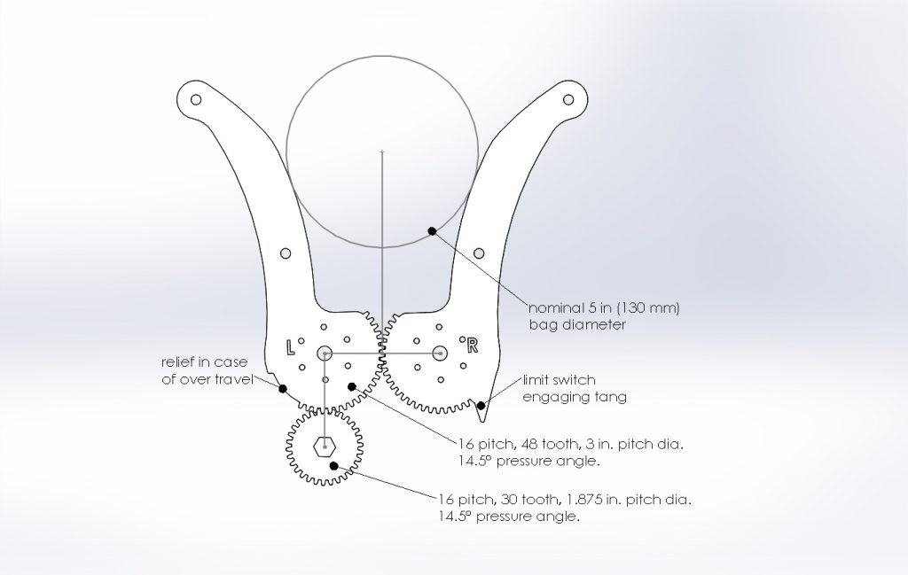
- Big gear (bottom of arms): 16 pitch, 48 tooth, 3 in. pitch dia., 14.5° pressure angle, 0.25 in thick.
- Pinion dear (driving): 16 pitch, 30 tooth, 1.875 in. pitch dia., 14.5° pressure angle. 0.5 in thick – this is to accommodate axial misalignment with the arms’ gears.
- Gear ratio: 1.6 (arm/pinion)
- Based on the estimated torque (τ) of 10 N-m per arm, given in Power Calculation, divided by the gear ratio, we arrive at 12.5 N-m applied to the pinion of diameter (d) 0.0476 m (1.875 in) with pressure angle (φ) of 14.5° the net radial load (F) on the pinion is given by: F = 2τ/(cos(φ)d) = 2*12.5/(cos(14.5)0.0476) = 550 N.
- Also, for a handy diagram see Engineer’s Edge.
- This radial load is applied to the pinion approximately 2 cm from the face of the gearbox which results in a bending force on the on the gearbox shaft that must be withstood by the gearbox bearings. Consult your motor manufacturer.
- We have created a Gear Torque and Speed Estimator Spreadsheet, available in Downloads.
- Material choice is extremely important – we prototyped, based on the materials readily available in the shop. Arm gear and driving pinion life must be checked for wear and fatigue, as a function of your material selection and width of parts. (Note: this is an oscillating load with force on the in stroke, while the return stroke is nearly unloaded.)
- Aluminium is not recommended. We recommend steel gears, but not stainless as this will gall/spall. Hardening the steel gears and adding lubrication will increase life.
- We have created a Gear Stress Estimator Spreadsheet, available in Downloads.


A couple of comments (cognizant that this is a prototype which may not contain all intended features):
1) I’d be concerned about the BVM coming loose and moving up out of the arms of the device
2) I have concerns about the fatigue and failure of the gearing over long duty cycle and prolonged use, if the gearing were made using either 3D printing or laser cutting
Related:
3) I’m curious if you have any thoughts on alternate mechanical compression techniques (strap around the bag connected to a rotating shaft, strap connected to a cam arm (https://the-air-project.github.io/2020/03/04/thirteenth_update.html), rotating cam similar to what was prototyped at MIT in 2010 (http://news.mit.edu/2010/itw-ventilator-0715), etc)
Some sort of cover to drop down on top of the ambu bag would be good to make sure it doesn’t come out when a patient tugs on the mask tubing.
How about just a velcro band to hold the bag between the two “jaws” or “fingers”? Quick simple and easily implemented.
On another issue when the design is finished we can provide assembly and testing in the Houston TX area. We manufacture, and design Measurement While Drilling equipment. It is small, has lots of electronics, and micro processor control needs so we have the right tooling and expertise. Let me know if and when you need to scale up. As well if and when you hit supply limits on the Arduino based boards. We design and build MicroChip based micro controller boards from components, so we have capacity, including programmers to move to this platform if other supply options dry up.
I am a class of 70 retired MIT EE alumni. I am using a fast linear actuator to compress the ambu bag. It is an off the shelf available part that can easily be controlled by an arduino or similar microcontroller. This approach might lend itself to more rapidly manufacture a simple emergency ambu bag compression “mechanical hand “ ventilator.,
If you email me at larrygessman@gmail.com, I can send you concept specifications and a demonstration video.
Hi Larry,
I’ve just sent you an e-mail about the ventilators.
hi larry i send email to you, look forward for your information
Please send prototype link
IsaactaylorManagement@gmail.com
Larry, I sent you an email for information. My thinking is the same as yours. Thanks.
Hi Larry
I sent you a emial today
Thank and best regards
Nolber
Hi Larry,
share the part number of the linear actuator? Maybe a photo of your prototype? the gearmotor and gears are my pet peeve.
I am in Sweden so euro parts are better for me.
Sam
I want to share a more simple solution. https://youtu.be/RVOna8jlPG0
Anyone thought compressed air solutions using air compressors?
And pneumatic controls might allow for some flexibility in throw force and velocity adjustment via cheap air valves and limit switches?
This would seem to replace much of the mechanism, have done more on this design?
Hi,I am a software engineer from Kenya and been following the build,I am really eager to know which type of differencial pressure sensor being used in this project
Hi Joshua, not sure you need a differential p sensor. May be able to use a regular p sensor. I have used, and will use again: MPX2300DT1
Can find them them at Digikey, Mouser, others. They are medical grade.
Use any socket with 0.05inch spacing (eg, found here https://www.digikey.com/short/zp4h42) if you like. Will need an instrumentation amp.
There is a link / pictures online of a (UK ?) team who built a device powered by hospital supplied oxygen. Saw the picture yesterday, but could not find it again when I just searched.
The source of ‘compressed air’ might better be the bypass nitrogen from molecular-sieve oxygen concentration, as many sieve devices require considerable pressure (>4atm) for high throughput.
It is still probably better to use a motor for this device, as modulation of the compression and release cycle is somewhat easier in principle, the necessary fine control over peak pressure is easier to make, and the results of catastrophic component failure are not as severe in geared compression as in pneumatics. (I suspect many forms of airmotor with the required characteristics might be noisier as well).
Fluidics might be useful, but most of these are currently industrial components that may not ‘scale to high production’ either quickly or well. I also see far more issues ‘down the road’ in maintaining proper integrity of a complex system that inherently relies on tube patency and integrity, and assured seals at connections, vs. simple wires, splices, and terminal connections.
A follow-on project that this effort might consider is the design of non-electric compressors for use in outbreaks where recharge of battery power might not be easily assured. While this could of course be implemented as straight electrical generation, the need for oxygen concentration might make some ‘pedaled’ combination of filtered-air compression and harvested electrical generation/transversion a desirable piece of portable, field-purposable equipment.
From the email response I received from this posting, many engineers around the world are interested in the linear actuator ambu bag compression design. It is practical only if manufacturers of fast linear actuators can quickly provide them in large numbers. The linear actuator needs to be fast (at least 4-6 inches per second) with 4-6 inch travel, 12-24 volts, preferably using a brushless, rather than brushed motor; which has limited, typically 20% duty cycle. Unfortunately, most linear actuators use brushed motors; designed for intermittent use. I am having difficulty finding a fast brushless motor actuator for this continuous use application. Slower but durable actuators could be speeded up via using a simple lever arm to double or triple their speed; but of course, reduce their force. A lead screw design could substitute for the linear actuator, but is harder to build; but still probably easier than the MIT design. Lead screws are available from Mc Master Carr, and many other manufacturers. As a solo maker, I do not have time to search the world for manufacturers who could quickly supply a sufficient quantity of fast linear actuators or pre made motorized lead screws that meet the above specifications. If you are interested in this design, please Google fast linear actuators or pre made motorized lead screws, looking for manufacturers in your country who have them on the shelf and /or could provide them quickly in large quantities. Please email me at larrygessman@gmail.com if you find any. Thanks.
You might want to try a linear servo control instead of an actuator. An H-bridge drive circuit should work as long as you can manipulate the encoder signals with the arduino.
Hi Larry,
I’ve been reading through some of your comments. Even though I have CNC machines, I have designed a simple and durable Z-lever mechanical set-up. It’s made out of readily available metal flat-stock and does not require any fancy tooling. Please look at my video in the link
https://youtu.be/IcB3SJZ6OQU
Hi Larry,
I just ordered two SUPER500 servos from Hobbyporter: https://www.hobbyporter.com/hobby-porter-super-500-high-torque-metal-robot-servo-12-to-24v-500kg-uav-education-industrial-motor_p1121.html
Will experiment. See what you think of these. Optical position info (no pots). 500kg-cm.
This will certainly work and will simplify the control circuit very much. I have experimented with 60 kg-cm servo; torque wasn’t enough but worked half-way
Hola saludos desde chile, estoy en cero, tengo Arduino, se programarlo, podría fabricar las piezas con una impresora 3d pero necesito los planos del mecanismo, especificaciones del motor.
Hola, el motor es de la compañía Andy Mark, y el modelo es el AM 3656 de relación188:1, puedes buscarlo en https://www.andymark.com/products/hex-pg-series-gearboxes-options
Angel Estrada (México)
Saludos
I wonder if there is some kind of accordion style diaphragm that is commonly made. This would kill the need for a fast linear actuator.
Why not use accordion bellows instead of an ambu bag? Not everyone is going to have access to a hospital or an ambulance.
Hi Larry, I ‘ve sent you email about the ventilator. Pls send me your suggestion !
Hi Larry… Jut sent you an email about the ventilators…
hi larry i send email to you, look forward for your information
apone@bitri.co.bw
MIT is doing a good job of covering all the bases needed to make this a reality. However, the aspect of needing gears is over engineering the design. How do I post a much cleaner solution using fewer materials for consideration that can use the current circuit schematics?
Can you please post it here or in a place where I can see it? We are working on a solution to this problem that can easily be implemented without too much complications.
We can probably 3D print the gears in metal. I’ll try to take a look at it.
Does anyone have any idea what the loads on the gear teeth are? Are there any design verification packages in existence?
I’ve also had experience CNC wire EDM’ng gears out of plate with great success. Hopefully that is being considered.
Check out http://www.isinnova.it/easy-covid19-eng/
These guys have developed ventilator masks and have freely shared the file for realization of the link in 3D printing. The clarify that the a patent will remain free to use.
Very useful link. Thank you.
why not 3d print in plastic? i am just eyeballing here, but think those solid metal gears are serious overkill. the bag is meant to be held and pumped in a single hand.
the human hands are not compressing the bag 2 weeks in a row. Better metal than plastic. It might be better to machine a rod of gear orientation and slice them as needed. What eats time are the tooling change overs.
How about aluminum extrusion for the gears. Simple tooling and no machining just CTL.
The source of ‘compressed air’ might better be the bypass nitrogen from molecular-sieve oxygen concentration, as many sieve devices require considerable pressure (>4atm) for high throughput.
It is still probably better to use a motor for this device, as modulation of the compression and release cycle is somewhat easier in principle, the necessary fine control over peak pressure is easier to make, and the results of catastrophic component failure are not as severe in geared compression as in pneumatics. (I suspect many forms of airmotor with the required characteristics might be noisier as well).
Fluidics might be useful, but most of these are currently industrial components that may not ‘scale to high production’ either quickly or well. I also see far more issues ‘down the road’ in maintaining proper integrity of a complex system that inherently relies on tube patency and integrity, and assured seals at connections, vs. simple wires, splices, and terminal connections.
A follow-on project that this effort might consider is the design of non-electric compressors for use in outbreaks where recharge of battery power might not be easily assured. While this could of course be implemented as straight electrical generation, the need for oxygen concentration might make some ‘pedaled’ combination of filtered-air compression and harvested electrical generation/transversion a desirable piece of portable, field-purposable equipment.
Chad,
I work for Designatronics – a 70 year old manufacturer of precision gears, belts and pulleys serving the medical industry. You will find our products in Coronavirus testing machines, surgical robotics and laboratory diagnostic equipment. Places where precision is important. We manufacture here in NY. Let us know where we can help. http://www.designatronics.com
What about using pneumatic actuators to compress the bag? This would eliminate the need for gearing entirely. A single compressed air supply could be used to drive numerous ventilators. The actuators could be 3D printed and eliminate the need to source motors.
Looking and not seeing, forgive me if it is somewhere here. I think pneumatic – not actuators, but bladder. Something like a blood pressure cuff around the bag. A simple air compressor and 2 way valve that would inflate (provide the “squeeze”) and then deflate. No parts that can wear other than the valves. It can slide over the end and would be regulated with the same electronics and sensors. Quick install and quick replacement if needed.
No need to “go around”, just contain it in a box. A bladder in a box (pelican case) side by side with an ambu bag, 12v DC air valve(s) (common commercial product) on a simple digital timer box. When the bladder is “dumped” the BVM will self inflate.
Additional: multiple air valves will increase/decrease the rate of flow in a predictable ratio, bladder can ran directly off the compressed O2 with it’s “dump” being vented into the BVM reservoir, entire electrical system and actuation can be easily replaced with mechanical timer and lever opened valving if you really wanted to go low tech.
how about slight modification of your idea: one or more bladders inside a large diameter tube – could even be made from used corrugated cardboard boxes. the bladders could slide in from one end. cardboard available everywhere. pelican cases are fantastic (great to build a self contained system into), but expensive.
Yep. Same page. A thought.
Related question: Whether motor driven or pneumatically driven or squeezed by human hand, doesn’t the bag ultimately fail around the stress points of applied pressure (plungers / fingers) ?
How about the concept of iron lung: The BVM / Ambu-bag placed into a sealable box, compressed air piped into box around outside of bag, compresses the bag (clean air pathway) – and when valve opens, ambu-bag expands.
The iron lung concept would apply pressure uniformly to the whole ambu-bag.
Need an ambu-bag engineering materials expert for this aspect.
and obvious drawback is NOT as easy for nurse/ etc to grab ambu-bag & squeeze if system fails.
Hi,
I had the same thought. How about a “scissor” arrangement for the pedals? The reciprocating movement could be achieved through double acting cylinders…?
For those designers wishing to use fast linear actuators and servos to compress an ambu bag, go to progressive automations on line. They have fast 12 volt actuators capable of speeds of 3 to 11 inches per sec at different force levels, some directly compatible with arduino controllers (which they also sell). Fast linear actuators and linear servos with control circuits are available from many other manufacturers; making it an off the shelf, available reliable drive system for ambu compression ventilators without the need to do sophisticated mechanical or electrical design to rapidly produce ventilators. Email me at larrygessman@gmail.com if you want to see a demonstration prototype of a linear actuator driven ambu bag ventilator, and a prototype of a bellows ventilator (made from a $8 disposable toilet plunger bellows also readily available from many manufacturer). The bellows only require minor modification to make them suitable for a ventilator.
Awesome, I emailed you. Send me a link if you get a chance.
Another simple idea would be to add a raspberry pi 0 to the electronic circuitry to allow for quick and easy remote monitoring.
There will be competition for ventilator manufacturers to get ambu bags. What if the company trying to manufacture a simple ventilator cannot get this part? A linear actuator compression design can be built to compress either an ambu bag, or bellows. Surprisingly, an mp100-1 toilet plunger is a plastic bellows that can be adapted to be a key part in a simple ventilator. It would be a disposable part when ventilator is used on a new patient. It could be quickly swapped out of the compression device if it fails. I doubt there will be an run on this part, which is now readily available. Linear actuators and servos are also readily available parts from many manufacturers (i.e. see progressive automations website for fast 12 volt linear actuators compatible with arduino or other controllers). Email larrygessman@gmail.com to see a video of simple design to compress either ambu bag, or bellows.
I guess I had imagined that the hospital would supply the bag since it is typically found near every hospital bed.
Can you sen us More info about your design, materials and More, since we would like, if posible to implement it in our country. That has hit by covid-19.
I’m from UK but in India, a medical guy not an engineer – can anyone send me a design which can be used as CPAP or in CPAP mode, standard components, ready to scale?
I’m in Delhi India Standard Time whatsapp +447765477305
can supply silicon rubber for BVMs bag valve masks – does anyone have a shortage?
https://e-vent.mit.edu/clinical/non-invasive-ventilation/
Is there an alternative to silicon rubber for the bag valve mask?
Could you use a linear actuator?? No position info, but maybe a pot installed directly on the shaft of one of the arms that squeeze the bag, read by the Arduino, would give you pretty good position information (after all, that’s how many servos get their angle information). Also – would a good, metal-gear servo do the job? Trivial to control with the Arduino.
https://usa.banggood.com/1500N-12V-4681012-inch-Linear-Actuator-Adjustable-Actuator-Tor-Opener-Linear-Actuator-Motor-p-1115476.html?rmmds=search&ID=565498&cur_warehouse=CN
Ya intente con correa alrededor de la bolsa conectada a un eje giratorio, correa conectada a un brazo de la leva y la fuerza que debe hacer la correa es mayor que con el sistema de piñones, el motor se frena.
I understand there is a concern that the acrylic is cracking over hours of use, and you are considering replacing some or all of the acrylic with aluminum. I am concerned the aluminum may not be much better with repetitive stress.
Could you stay with the acrylic fabrication you have, but reinforce with off the shelf flat steel those places where the acrylic can’t carry the repetitive stress? For example, if the cracking occurs at the hinges, extend the hinge pins by a few millimeters on each side, and attach a flat steel bar (e.g., google “Zinc Steel Flat Bar”) to the acrylic on either side so the steel carries the hinge load rather than the acrylic.
Using off the shelf flat steel (you’ll find it quickly at Google), you don’t have to change the acrylic fabrication. You just need to cut, drill, and attach.
I personally believe the solution is increase factor of safety – do not optimize, we do not have time to optimize. That means use 0.12” aluminum sheet metal if at all possible. Cheap and structural.
using the acrylic fabrication, initial 5 of 14 teeth are engaged. In the event of failure of the teeth is it possible to engineer faster removal of failed components and then simply advance the next 5 to engage with gear? (slide them forward). At that time one could then replace the five engaged teeth on the back end.
compliance will be up to 10x less (not higher) in diseased lungs.
I applaud all the work going into this problem. I see this device as working well for a patient who is fully sedated and pharmacologically paralyzed. However, these patients need to start breathing by themselves to be able to recover. If a patient has an injury – say a head injury – you can keep them sedated and paralyzed and breath for them almost indefinitely. But that type of ventilation is not good for a diseased lung – say with ARDS. For that reason you may want them breathing with supported effort at an early stage.
Once they start breathing it gets a whole lot more complicated. Synchrony of patient and machine is important of patients will “fight the vent”. They also cough which can be difficult to manage. A mechanical Ambu bag may not be responsive enough to this sort of patient. I worry that fighting the vent could worsen diseased lungs.
I feel there is a role for this but we will be a long way into the hole by that stage.
I hope this clinical perspective helps clarify some of the real world issues that ARDS patients face in the ICU and the engineering design challenges these present.
Thanks for your work on this.
Hey Ben,
Totally agree on your feedback. Two questions:
Do you think this device could have some utility as a bridge device that keeps patients alive while waiting for a better vent?
What are your opinions of this setup linked here? I’m trying to help an Emergency Department prep for the likely scenario where they get overwhelmed and have a shortage of vents and your clinical expertise would be greatly appreciated.
https://emcrit.org/pulmcrit/split-ventilators/
Hy Tyler. I’m an anesthesiologist so this is at the front of my mind right now.
As a bridge, I think this could work. I think we have to try it. My major concern is that I don’t see many ICU vents becoming available. The numbers out of Italy look like patients are on for 2-3 weeks. But we could bridge them and see if something comes through, fingers crossed.
There’s been a lot about the vent splitting across patients. This makes me sweat. The biggest problem by far is lung compliance. Laplace’s law means that a smaller stiffer lung unit will collapse and send volume to an inflated lung unit. Lung compliance changes with the disease. Balancing two patients would be extremely difficult. More than two and you are in tiger country.
This is such a daunting task. I really admire what you’re doing. We are doing something similar and may perhaps have a chance to collaborate sometime (virtually, of course!)
Hi Ben.
I’m concerned about the device’s ability to meet all the modes and demands of modern ventilators in a useful time frame. Could there be a specific range of capabilities that this could be tailored to fill freeing up full featured machines for those in need? If so, this might help the team get to a point of utility earlier on in development.
Ben and Tyler,
We are a team in Houston not from the medical industry – Oil and Gas. We build high end electronic/mechanical systems that go down hole. We have the capacity to design, and build from the chip level not having to use an off the shelf controller board. We have programmers to program the control circuit.
We had progressed along in our own project using a Ambu bag, found this site and thought ok we are at the same point – a potential design at the stage of testing, so we decided to drop our design efforts and throw in here. Reality is the design is the easy part. Supply chain, and getting a manufacturable design is the real issue. There are likely only a few thousand Arduino boards in inventory at suppliers across the country, this is the major challenge, factoring in supply chain limits and designing around available inventories. Can’t seem to get through to anyone on this site to see if our expertise in taking protoypes to market can help. Your combined input would help us, our concept was to add flow and pressure sensors to the system so that the computer controller could vary the rate, flow, and pressure of the output from the Ambu bag. We were trying to get as close to the high end machine as possible with the limits of the Ambu bag base of the system. Would love to connect via e-Mail to discuss. As well if there is an panel member monitoring this would love to connect maybe you have a plan failing finding out we will move on.
hay,i’m an me engineer in WuHan China. From the begining of this disaster, i am an volunteer in helping local medical team.
i really want to help
it seems there is a large mount of Arduino boards production in China,check this url for example:https://detail.1688.com/offer/592957830382.html?spm=a312h.2018_new_sem.dh_002.1.4ae042c96WKHEp&tracelog=p4p&clickid=a7242f7a415c4711be55c80766cd2798&sessionid=c68819bc259e9540400768cb96dfd63b
if any help i can provide,contact me via email:xch5716@csepdi.com
hi xie,
i just send to your email regard arduino
haven’t you given enough to the world?????
Good points in scaling. Lots of ideas here. I ready with boots on the ground and tea in the kettle but I see conflicting directions. I certainly want to help and looking to make something useful in the field. Can we get some moderation and move this to a better platform?
Rob,
A potential solution to the Arduino problem would be contacting all the Maker Groups. Their is one in every major city, and they have boards there as well as can do a call out to their members to donate their boards. You also have robotics clubs in the high schools and universities and colleges. They have boards. At UMKC, one of the freshman classes requires you to purchase a SparkFun Inventors kit. If UMKC does this, others may as well. Each of these kits has a board in it. The universities and colleges that have these can then shoot out emails to students that have been/are enrolled in the course and get their boards. The point being, there are a lot more boards that you think, it will just be a coordination effort to get them. The news outlets can even help by talking about this and leaving a link up for contact to get the boards where they need to go.
You also have to remember that there are Arduino minis, Pi’s and PI minis out there that can be used as well and the code wouldn’t need to be changed much. That opens a whole new venue to get boards.
Here is another. While I cannot mass produce boards, I do have the materials to make my own boards in a way to fit the item I am making and it is an Arduino in everything but name. There are a crap ton of makers out there that do the exact same thing as I do. So this gives even more options as we can make and mail boards or send the parts to whomever can make them.
So as you can see the boards wont be an issue as far as being available as much as a logistics issue to get them to whom they need to go to, how to get them there and how to coordinate this so that it is an effective solution.
Hi Ben Moor,
I don’t normally reach out like this, would you happen to know how I could help manufacture ventilators in the US that are approved for hospital use? I am not interested in making any money on this. Only I fear for all the patients that will soon need ventilators. I hope to hear back from you soon.
I am a Senior Mechanical Engineer who wants to contribute however possible during this tough times.
I appreciate if you could forward me to the correct person to talk to if you know of a better person.
Best Regards,
Benoit Belley
Hi Benoit, please email me at sid@atreya.vc we are trying to use fibre glass instead of acryllic for making the prototype for testing before final production. Would welcome your feedback for producing the gears.
Couldn’t check valves mitigate this risk?
Hey Ben,
Since you seemed to be experienced with patients using ventilators, Do you think, in the specific case of COVID19 patients, the other end of the AMBU bag needs to be attatched to an oxygen rich supply of air or is an open end sufficient?
Ben / Arya:
I’m concerned about what the expiratory limb is connected too, also (Another anesthesiologist talking here). Aerosolizing viral particles into the environment is a real issue. This can be mitigated with filters, suction, but I can’t tell this from the diagram (the Y-tubing is shown, but not the end of the expiratory end.) How is that setup?
Hey Ben could you help me understand where the exhalation air is going? I have built a ventilator that meets all the design criteria shown on here, but I can’t get comfortable with the exhaust part of the equation.
I read a paper that a team used resistive strain gauges to monitor chest expansion and compression. This could be used to improve the ventilator synchrony. A cough could be determined event duration. I’m no expert just throwing an idea out there.
http://www.nature.com/articles/s41746-019-0083-3
Nice!
Much of the necessary work, including some developed circuitry, exists in the first generation of ‘scam’ SIDS monitors. Some of these used a plethysmograph band to detect and discriminate kinds of respiration (in part to determine different kinds of respiratory distress noninvasively) and were capable of some analysis of the resulting ‘waveforms’ both for artificially-intelligent analysis and data forwarding to more expert personnel.
In cases of advanced ARDS, where account of both the patient’s efforts and the required oxygenation/gas exchange mass flow need to be carefully taken, I think either an electrical or plethysmographic tracking of diaphragm action (rather than just ‘chest expansion’) would be of benefit.
Cough response is not something the current design can accommodate; it will have to be done either via an arrangement like the venturi tube used by Percussionaire, or some other means of passively regulating peak pressure without exhausting unfiltered virus particles. The cough or sneeze response to the Ambu-bag compressor is probably to reset stroke to full bag expansion and hold xxx ms. to re-establish differential pressure loop control. Some of this also depends upon the specific mask design used, which I think has not been ‘frozen’.
This is an important point. Ideally the model will allow for return of spontaneous ventilation and synchronicity of respirations with the patient. Perhaps the engineers can review the idea in this article https://www.ncbi.nlm.nih.gov/pmc/articles/PMC3339758/ describing a modified ambu bag which detects and measures spontaneous respirations. It uses an incentive spirometer to measure spontaneous respirations. The challenges for this design would be maintaining peep/pressure support in the spontaneously breathing patient and maintaining filtration of exhalation.
Also, note that the in the operating room, patients breathe spontaneously on our anesthesia bag on a circuit with a pressure valve placed after the exhalation bag..it has a much different compliance than the ambu bag. The problem with the anesthesia bag is that is not self inflating.
We are working on an “assist control” mode that will follow a patient’s breath rather than trying to breathe against them. Should be ready for the next controls system release.
Would following a design similar to the second stage on a scuba regulator work to allow the patient to “demand” a breath?
Maybe using such a value to trigger the compression of the ambu bag?
Any thoughts from a doctor?
Steve: how would this differ functionally from what is in use on bilateral CPAP (already discussed as a potential solution in the functional ventilator shortage)?
Hey guys,
Quick suggestion of some guidelines I’ve used in high stress cycle medical devices in the past. The average recovery time appears to be 6 to 8 days on a vent. Given that, if we assume a patient needs to survive of this device while highly sedated or paralyzed until a conventional vent become available, we can assume we need this device to be a bridge for at least 8 days, if that’s the main utility of the device. According to the EPA, a person takes on average 23,040 breaths per day. So that times 8 times a rough engineering safety factor of 1.5(non ideal but acceptable given circumstances) means we need to verify if this design can stand 276480 breath cycles in order to ensure durability of the parts for at least one patients cycle. It may be easier to make less durable, easier to swap parts but thought this rough cut math might be helpful.
I am a physician in addition to class of 70 retired MIT EE. Non medical designers of simple ventilators need to be aware of the medical facts to guide their design criteria. A medical outcome paper just published in Lancet. Of 37 ICU patients placed on ventilators, only 7 (35% survived); 30 (94%) died. Mean duration time to death was 7 days (range 3 to 11). I suggest that simple, ambu bag compression ventilators may be most useful on sedated patients who will not compete with their own spontaneous breaths. They “mechanical hand” mechanism should be durable enough to last 11 days. The disposable ambu bag or plastic bellows, if damaged over time by the compressor, could be changed out as needed; relaxing the design criteria a bit. In poor countries, designing these devices to USA FDA specifications for rapid deployment may not be possible; so this data may help designers cut some corners. In the situation of extreme ventilator shortages, I am sad to say that doctors could triage the sickest patients who are likely to die to simple ventilators, sparing them the ethical decision of stopping life support. Those patients more likely to survive could then be triaged to full featured ventilators capable of weaning a patient back to spontaneous breathing. For more information on my very simple designs using linear actuators to compress disposable ambu bags and bellows, or designs that can breath for several patients simultaneously, that filter expired air with hepa filter material obtained from hvac filters, or any questions, please email me at larrygessman@gmail.com
Can the Ambu bag be replaced with industrial rubber bellows that are secured to the Intubation tube with a clamp? Might that be easier to actuate and control with hydraulics?
no, those are neoprene rubber and contain chlorine.
sorry – finger fumble
1) cont’d
increasing gear radius by a factor of 2 will decrease stress by a factor of 2. Generally every 10% reduction in stress gives you a 2x increase in life (i.e. number of cycles to crack initiation). this is the rule for metal, in plastics it tends to be even better (i.e. 10% stress reduction = more than 2x life). by this estimate increasing gear size by 2 will extend the life by a factor of more than 100.
2) consider a different material
a) I disagree with the comment above about aluminum. Alum would be much better than acrylic. While alum is subject to fatigue (tendancy to crack after repeated cycling) it will be MUCH stronger than acrylic – quick search shows acrylic endurance limit ~1.5 ksi, Alum 5-10 ksi. (endurace limit is the stress at which the material can cycle ‘for ever’ and not crack)
b) ALum or other sheet metals can be quickly cut on a water jet or laser cutter, or if you have time to set up tools – stamped. I can point you to Boeing experts with decades of experience in any and all of these methods if you are interested. They would be honored to be asked.
3) the failure is likely fatigue, it may be something else arising from the high contact load at the gear teeth. Gears are notorius for “point loading” where the surfaces touch. Acrylic is a particularly brittle flavor of plastic. a more ductile (rubbery) material might fare better. But again stresses will have to be significantly reduced.
I don’t speak for Boeing but I’m a technical fellow there. And I know a lot of other tech fellows who know a lot about quick, effective, practical solutions. Ask me anything and I can tap into that network. There are a lot of us sitting at home in teleconferences itching to do something helpful.
1) increase size of gears – change shape of bag compressor arms to compensate
Cover the gears to protect from foreign objects?
Yep, final designs will not have any exposed gears or pinch points. This is important for both foreign objects, but also for protecting the bag from being shredded. Good insight!
4) There may be better alternatives than gears. Belt on cylinder? Bicycle gears/chain? Wheel on wheel with high friction contact and spring-loaded contact force? Bars and hinges?
If you are going to make 700,000 of these things then you need to accommodate multiple types of drive and motor.in the final design. Nobody will have 700,00 motors or gears in stock. Bicycle chains, gears, tooth belt drive, geared and non-geared motors both stepper and brushed or brushless all need to be ultimately usable.
I realize that you are at prototype 002 today but please think about different ways to achieve the same mechanical end by using different motors and drive mechanisms going forward. The same applies to software and processors.
Lastly reduce the number of moving parts to a minimum. The original MIT ventilator only had one moving part, the curved arm. The new design is far better but more complex to build.
Oh yeah, please make it run from a 12VDC source. Everybody has car batteries.
This machine will be a true lifesaver.
How about windshield wiper motors from cars? I would imagine that they could easily handle high cycles.
fantastic idea, they are dirt cheap with lots of torque
Windshield motors are one direction only and usually spool up for a cycle and continue until the cycle is complete. Another source of high torque, gear reduced 12 volt cheap motor that has the added benefit of being controlled anywhere in it’s cycle as well as reversible is a power window motor. It does not have an integrated position sensor but if mated to a PWM style sensor can be controlled by voltage as well as having the simplicity of a brushed DC motor and not require a controller circuit like a stepper motor.
Had another thought, in a high oxygen environment is it really wise to use a brushed motor due to sparks? Something to think about. The complexity of a brushless motor may be worth it?
Hi Andrew, we need help selecting DC motors, would be amazing to get your assistance. We were also thinking of using PCB material instead of acrylic or aluminium. What do you think about that? Please email me at sid@atreya.vc
Andrew, this might work for you.
https://youtu.be/evWKC7D35AE
5) seems like the most expensive, and hardest to get mechanical component is the electric motor. What if the motor were replaced by an AC-powered drill. Advantages: cheap, readily available in quantity, built in reverse, high power. Disadvantages: needs a more complex control system – replace trigger with electronic control, likely need an output rotation sensor and software to control it. Need system to reliably switch direction or rotation (can this be done electronically by reversing polarity or is a mechanical system like a servo required to move a gear?). Lock into one drill design to standardize – what is there most of at the big box stores? Strongly recommend that the electrical system be designed to accomodate whatever piece of equipment will limit the ability to widely/quickly produce. Seems like this would either be the motor or the Arduino board. Design for manufacturing. Talk to your manufactures now. Talk to your suppliers now.
Battery cordless drills, I’ve used a couple off the shelf for projects. Cheaper for the drill skin than it was for the equivalent motor locally. Have used the 18v ones for 5 and 12 volt applications, they are robust, plentiful, though noisy… And almost every store in the world has at least a few, if not more…
Jon-Paul, I agree. I’ve looked for suitable industrial servos and rc servos. The ones that fit the 15Nm requirement are few and expensive, while cordless drills average better than 10Nm, and 15Nm are common. Many 12V models can use the car battery idea. The chuck can easily be removed on most. The driver can be an L298 to control direction and an arduino/raspi/etc can provide PWM velocity control. Using both sides of the H bridge allows max 4 amps. I think that 36watts should suffice ( of course needs testing ). Encoders can be connected but I think the actual arm position is best sensed at the arm ( rather than at the motor that moves the arm ), so physical manually adjusted limit switches that are set by the clinician may be simple enough.
Thinking about a source for 100,000s of small, powerful, durable DC motors. Cars have several: wipers, windows, tailgates, sliding doors, HVAC, air suspensions, seats, etc.
Sales of automobiles have collapsed. February 90% drop in China was widely reported. The US can’t be far behind. The auto industry should be able to supply vast quantities of new, small, high-quality motors stat. The auto parts industry must have even greater quantities, and even if at lower quality, they are likely designed for much higher stress and more cycles than required here.
Andrew: I think the gear speed is less critical than the tooth profile and surface finish. We’ve seen proposals here to 3D-print the gear teeth, which would logically involve the ‘brazed’ stainless microspheres in some metal co-binder that was used for the NASA rocket-nozzle printing contest. I have my doubts that the surface-finish characteristics of this will tolerate long-term contact even with ‘appropriate’ tribology unless the tooth profile is reasonably fully epicycloidal (like watch and clock gear teeth, so there is rolling contact only for the whole range of powered engagement). Adjusting the ratios to produce the necessary mechanical advantage while optimizing the load on all the respective ‘tooth pairs’ is probably the design criterion I’d recommend.
Alternatively, some method of assuring or improving the effective surface finish, or treatment after fabrication, could be considered to get the required indefinite long life out of at least the most highly stressed gears in the train. I’m not directly familiar with the practical surface finish from reductive wire EDM, or whether post-machining hardening would be required to give the necessary wear resistance. I think we already have commenters with industrial distinctive competence to recommend best practices in this rapid-design project.
Hi Robert,
Not to push a Swedish manufacturer, but Höganäs has a Digital Metal 3D printer that can do stainless steel with 35 micron resolution. No idea about throughput and machine availability though.
In FFF / FDM printers, SLS printing at 150 micron layers would usually result in a better surface finish than a comparable layer height. An SLS printer creates approximately rectangular layers, meaning the layers are much less prominent than with FDM on vertical surfaces. Extrusion-based printers produce ovoid layers where the curving surface makes the layers more transparent and prominent at the top and bottom. I read here (https://printerhow.com/led-vs-laser-printer/)When it comes to surface finishing by 3D printing technology, layer thickness is not everything.
People still remember who to get and compare Cricut vs. Cameo. We appreciate your time and feel that your time is important. We give you all the key distinctions between cricut vs cameo at topvinylcutters.
These are both cutting machines which are considered to be the best. But the artisans want the best machine and still want to equate the silhouette with the creator of cricut.
Not related to ventilators, but for other areas of potential safety protection…
And it offers a good reminder to using proper materials and processes for an application as well as seeking requirements and validation before going into production.
https://blog.prusaprinters.org/from-design-to-mass-3d-printing-of-medical-shields-in-three-days/#_ga=2.26199293.1726437079.1584983876-1079568191.1584983876
If computational models are being used to validate the safety and effectiveness of the ventilators, the attached industry document provides some guidance.
Attached is ASME document V&V 40-2018 “Assessing Credibility of Computational Modeling Through Verification and Validation: Application to Medical Devices”. Examples in this document include artificial joints and patient beds. Thus, I believe ventilators would be included.
Medical devices are classified by the FDA based on risk to patients, which requires a greater level of evidence to demonstrate the safety and effectiveness of medical devices that pose a higher risk to patients. Analogously, this document focuses on developing a risk-based approach to determine the level of V&V needed to support the use of a computational model for evaluating device safety and/or effectiveness.
I am working with a multidiciplinary team in Peru to design anf fabricate a similar system. We have two questions:
1- Have you thought in any way to measure the % of O2 that you are giving to a patient? We have been talking with hour Ministry of Health in order to validate the characteristics we are proposing and % of O2 is somehow critial for patients with ARDS. We are still solving this issue.
2- In the pictures we have seen until now, the expiratory valve is part of the ambu, after that you connect a tube that goes to the HME filter and then to the patient. During exhalation, have you considered the volume that will be inside the tube when an inspiration starts? In essense, the amount of CO2 that would go inside the patient again? Because of this we are proposing two solutions, the first one would be moving the sensors and the expiratory valve near the patient, the other one would be using different channels for inspiration and expiration with a Y connector / valve, but that would increase costs beacuse we would need two sensors for each one we had.
im an me engineer in wuhan
i help in local medical team
O2 is important
i found that, Ventilator should be connected to oxygen cylinder to provide high flux O2 to patient.
We use gas detectors in heavy equipment industry to detect dangerous environments. A cheap detector will do CO2, O2, CO for around the $100 range US.
Here is one from Amazon
https://www.amazon.ca/Quality-Pollution-Multifunctional-Detector-Occasion/dp/B0831HF99X/ref=sr_1_6?keywords=gas%2Bdetection%2Bo2%2Bco2&qid=1585671996&sr=8-6&th=1
Robert: I share your concern with brushed motors, and relayed this directly to the team via e-mail a couple of days ago. A different approach (if, for example, the repurposed automobile-component motor approach is followed) might be to design effective enclosures for these motors that have appropriate heatsinking, or flame-arresting mesh in intake and exhaust for their cooling; this might be as simple as ‘weldable’ cut plastic sheet plus some simple 3D-printable vents with screening.
As far as gas detection: there are existing tuned-laser-diode methods for measuring ppO2/CO2 noninvasively (via subcutaneous blood color!) that can track the actual patient blood-gas concentrations rather than inlet-gas (which this design cannot effectively modulate at present) and developing such a thing in modular form may represent a better intermediate-term solution at very low per-unit cost.
Are the CAD files available so I can better evaluate the design?
Also, we have access to two Markforged Mark II 3D printers which can print gears and hinges in continous carbon fiber reinforced – carbon fiber embeded nylon. We use it routine in FIRST Robotics FRC robot designs which prove incredibly resistant to breakage.
Are there any cad files available? (Using Solidworks 2017)
They posted a set of DXF files today.
https://e-vent.mit.edu/wp-content/uploads/2020/03/MITeVentDXFs.zip
Can someone manufacture this ? I can do all electronics and software, but I cannot do the mechanical stuff myself.
I can pay for the parts and shipping.
I would like to build one here so I can work on the software and electronics.
Hi Bertrand Achard
I’m an entrepreneur with more than 25 years of experience in Instrumentation & Software Industry. I have worked with various sectors like Automobile, Defense, Aerospace, Semiconductor in India and Abroad.
Im very curious and closely following this. Reliability,supply availability of electronic and control boards in volume is a main concern for me. I can build all all mechanical system with very high accuracy and precision for you.
But Im thinking of replacing aurdino with some serious industry grade SOC board. And motor, gearbox and drive from one of my aerospace supplier.
Whats your view on this?? We can see how we can collaborate, leverage our expertise and contribute
Regards
N.Kashyap (n.kashyap@midas.in)
Hi! We’re forming a team around Mumbai, please check our profile for contact details. we’re looking to build a prototype and need help with Mechanical RnD. Please contact us ASAP
Note we made these arms out of waterjet stainless steel. We have never tested this shape in plastic, so you may need to modify the design to accommodate your material specifics. Thanks!
I would like to see the CAD files too if those could be posted, please.
Thank you!
CAD will be up very soon.
Hi all, my understanding from the comments mentioned above is that the ventilator used for ARDS assists patient’s breathing and requires flow sensing, which is not included in this device. Am I correct?
Hi from Colombia!
Here we are run out now of ventilators and respirators, please free the resources now!
Don’t wait for approval or in private please!
We at School of Engineering of Antioquia (EIA) can refine this concepts and ideas, and adapt to our own resources, all credits yours if you want!, please for love to god! help us!
Mauricio Henao, My name is Antonio Gomez i am located in Cali, Colombia i have a company that has sourced many tech items from china and the USA like arduinos small engines and different devices with a large experience and background in international business and protect management specially with start ups and new products. There is also a group at UNiVALLE leaded by Ricardo Ariel Rodriguez attacking this situation I want to offer my help to try to coordinate this effort in colombia please contact me my cell is +573102236343 or email organicaltda@live.com
can I have your Number or WhatsApp? my WhatsApp is 4048201800
Hi Mauricio, The resources you need on here have been made public and are available. However, keep in mind that this is an experimental project and as you’ve read, several medical practitioners have made clear of the issues this system has especially in a diseased lung as evident with Covid-9 patients who require respirators. Being in Colombia right now, I have seen several designs and I notices a lack of clinical considerations in the design. All I see is guys working on modified air compressors (rotary screw) and getting massive media coverage and accolades of being heroes.
This concerns me greatly. I see the urgency but I worry that good engineering practices might be shelved for expediency. A lot still has to go into this project to became useful in the context of today’s need. If you need my input, you know how to reach me.
An arm connected to an electric drill could work well? Big drill availability worldwide. Can run on slow speed & reverse it. Challenge is control circuitry (arduno?) and no doubt the interfacing would vary between manafacturers….
I’d be interested to see how using a BLDC with reduction gears connected to an O-Drive and RaspberryPi would work out. I say this because for example you could use ROS to control the motor with feedback/encoders and maybe incorporate sensors to adjust params like pulse and airflow rate.
Si son humanos, liberen los archivos CAD por favor, desde Argentina ayudemos a las personas!
Gracias
I’m curious to review your other concepts with you as well as the selection criteria that was used that resulted in moving forward with this particular prototype.
Some general comments:
1.It is REALLY important to document ALL requirements ahead of time, specifically High level Key Performance Parameters, these will become the criteria against which the concepts are measured. [E.g. interface with existing manual ventilators, low noise, high reliability, non-toxic]
2. Start with functions and develop as many as possible concepts (at least 50) for each function. [E.g. Squeeze, Control, Power]
3. Then evaluate each concept against the criteria. (It might even mean building a few models to clarify unknowns)
4. Then mix and match the best concepts per function to build the system. Here is where the real synergy takes place when you realize the benefits can be compounded. [E.g. using a pneumatic cylinder to squeeze eliminates the claw mechanism and is easier to control]
The intent is to keep as many horses in the race as possible and eliminate losers along the way, as apposed to picking a winner in the beginning and then going into the endless loop of changes.
This might seem abstract at first, and even though you do most of it in your subconscious, it is important to write it down. It will bring newcomers up to speed quickly with what the goals are and document why certain concepts were eliminated to prevent rehashing.
Regards, Sean
Hi all, a small contribution to the problem with mechanical stress/wear of the acrylic parts. An alternative material could be POM. This material is much more ductile and can be laser cut and is actually used for the production of conventional gears. A drawback of POM compared to acrylic is price, so you might want to limit the use of POM to the gearing parts.
Best,
Richard Lekkerkerker (Amsterdam University of Applied Sciences)
r.a.lekkerkerker@hva.nl
Hi, in Lahore, Pakistan where I live, we face an acute smog problem during winter months and air quality becomes the worst in the world. This year I had a some success designing and selling a low-cost air purifier fabricated from acrylic.
In a poor country of 200M+ people, I am very excited to quickly get to work with manufacturing this e-vent for the resource-starved hospitals of Pakistan where little kids and family members take turns continuously pumping ambu-bags for their loved ones.
With my computer engineering background and links in local manufacturing as well as healthcare industries, the urgency to make this facility available trumps a need for fine-tuning robustness and other delicacies. In its most basic form this device performs a superior function than an ambu-bag being manually pumped by a child or a layperson.
I hope the team at MIT can help me with a few basic queries so I may at least begin sourcing some of the parts and materials that are needed, as Pakistan is in a state of lockdown and all markets are closed. Hence my desire to get to work asap!
Best,
Hassan Zaidi,
hassan987@gmail.com
Hi Hassan,
We have a team working on a lower cost and easier to manufacture version that should be available for download very soon.
Can you please tell us when the CAD files will be released. I’m very concerned about availability of ventilators in my area.
I can have my FIRST Robotics kids start from scratch…but that does not seem highly productive. I believe it would be better to work on one design, collaborate on improvements if necessary and product the best final product WE all can produce.
Also, some of my students and I spent yesterday comparing the strength of acrylic versus polycarbonate models (we typically use poycarb in FIRST FRC robotics because it’s more durable). Polycarb is indeed stronger and can be bent in a brake. However, it need to be CNC’ed. We have access to 4 CNC Router devices in our area and could produce parts.
Please keep us informed.
CAD should be up by the end of the day.
Can we get in touch by phone? I work with Smarter Every Day and we too are working on a design for a ventilator. We would like to get in touch and discuss the design and other things. Trent@smartereveryday.com
Dear Team:
First, thank you for your work. I’m one of several who have been alerted to the upcoming design and I am following the progress. We are preparing a team to utilize the design when it comes out. While I realize the need to roll out in a complete and verified package, I wonder how you feel about supplying a tentative BOM for parts and raw materials that will probably not change, .ie. for example 12V DC motor spec, aluminum sheets 0.25 thick, power supply 5W, Arduino board and controller etc. So we can get these items ready and know approximately what will be needed to make one ventilator.? Hope I am not pressing you, I am sure you are working very hard.
-Mariano Garcia, Ph.D. P.E.
Ithaca NY
Suggest use of a windscreen wiper motor which are reliable, cheap and readily available. Design validation of these motors >1000000 cycles
Rory, we are working on a wiper motor version. Will hopefully be available soon. The big challenge here is position tracking of the motor in order to accurately control tidal volume, and I/E ratio.
C U
This is a different Rory than who started the thread.
I saw what you said about the wiper motors. Here is a product that encodes the output shaft and comes with adapters for whatever size shaft. We have used these on our products and they are extremely dirt and liquid resistant because they are not optical based.
https://www.cuidevices.com/amt-modular-encoders
-Rory
Its here this will likely repeat across the country. ALBANY, N.Y. — Gov. Andrew M. Cuomo awoke before dawn on Tuesday, emerging after a few hours’ sleep to board a helicopter to New York City for the coronavirus briefing that has become a daily ritual for him and for the millions of people now watching.
But this event would be different. The outbreak was moving faster than he had expected, with the number of confirmed cases doubling every three days, and he decided he needed to show people — including the White House — how desperate the situation had become.
“You want a pat on the back for sending 400 ventilators?” the governor said, referring to a recent federal government shipment to New York.
“What am I going to do with 400 ventilators when I need 30,000?” he said later. “You pick the 26,000 people who are going to die because you only sent 400 ventilators.”
The governor repeatedly assailed the federal response as slow, inefficient and inadequate, far more aggressively than he had before.”
We had come up with our own Ambu bag based system but stopped short of finishing our prototype when we found this page, recognizing your design was close enough and our sensor and controller card concept would plug in. Besides the design is the easy part. Taking that to a product roll out will prove to be the largest challenge. There are likely only a few thousand Arduino boards in inventories across the country. Once those are gone you either identify alternatives or your system deployment stops. As the above indicates we likely will need hundreds of thousands of ventilators. We have experience developing supply chains as well as designing, and building electro-mechanical PCB based systems and then taking them into production. Time is short we have not been able to reach anyone in control of this event to discuss whether you need our help. We don’t feel there is much time to spend waiting to find out if this effort has all areas required to succeed covered.
Can we get preemptive design release? Here in South Texas I have a group of 6 trying to gather materials and check what each of us have on hand.
If we know what we need we can start ordering what we don’t have.
We understand the design is still in flux, but were wanting to get stuff going before everything in the city gets locked down.
James if you get a response please let me know I am trying to determine if this is an honest attempt to accomplish the stated purpose. We have a group near Houston we had developed a conceptual system and had acquired an Ambu bag. Then we found this page and decided that their concept was close enough to ours that our control circuitry (we had added flow velocity and pressure sensors to the loop) could be added on. We decided in the interest of efficiency to just join them and move to the next and most likely the largest challenge – supply chain. There will only be a few thousand Arduino boards in inventory. That won’t put a dent in the worst case scenario needs. We have a team with PCB design construction, and programming expertise. We will still have supply issues but we can retool using different chips and come up with numerous variations of micro processor board layouts to maximize the quantity of potential units. Our fear is this is just an academic effort and it will not have any serious impact. We are evaluating our next steps but people are dying in the world for lack of ventilators. We have contacted our representatives and have been given contacts to move ahead. That is likely the course we will take. Since you are also in TX we would welcome you to reach out and we can discuss. derivative.solutions.llc@gmail.com
Rob Kirky is there any way I can help? I am a senior mechanical engineer with over 10 years experience and looking to help out any way that I can. Can I email you?
Rob, We’re in the same industry it would appear. I’m also in Houston. I have extensive mechanical design expertise as well as design for additive manufacturing expertise. I’m taking a look at the gears now. I think we could print lightweight versions of these gears with enough accuracy that they could be built in ‘columns’ in Inconel 718 or 316SS and SAW/EDM split in large quantities. Also the design could be better balanced through the addition of an idler gear so that the left paddle gear isn’t carrying 2X the input load. I also believe much of the frame/paddle could be 3D printed in plastic or CF/plastic. The designs on this website are quite incomplete. I only see DXF loaded with profiles and they don’t appear to have all of the features defined and have extra features on them. Have you seen any better details.. an assembly maybe?
Hey Guys,
Live in NYC and looking to build/join a team to produce these mechanical ventilators.
I have connections to medical hospitals to test this on and have connections to the government to get these ventilators to proper use. Background about me i’m a computer engineer with a lot of experience in microcontrollers, embedded software engineering, and IOT devices. With the proper schematic design and team of engineers i think we can build this in NYC. I have connections to Columbia university makerspace where other engineers could help us build and parts we need mechanical, 3D, etc… Let me know if you know anyone in the NYC looking to do the same, and or any teams that have already kicked this project off locally. I think we need teams like this in every region to help in offesetting the number of ventilators needed for all our countries.
Hi, I am also in NYC. I am close to the elmhurst hospital. I recently got my bachelors in biomedical engineering. I have experience with PCB design, circuit design. I have mostly worked on brain and muscle stimulators but I am interested in helping any way I can. I also have experience with arduino python and matlab.
James Camacho, can we sync up? I have no connections to medical hospitals. Is there any way I can help? I am a senior mechanical engineer with over 10 years experience and looking to help out any way that I can. Can I email you?
Hello,
My company has mechanical engineering, manufacturing, and outreach/communications support we would like to contribute for this effort.
Are you available for a brief call so we can discuss how we can collaborate? +1-305-792-8778 emilio@soptechint.com
Here are some ideas for areas we can assist with:
– Technical design, assembly instructions, and shop drawings for manufacturers (we use SolidWorks 2019).
– Hosting webinars and creating email campaigns to keep people informed and generate more support.
– Government outreach. My company is based in Miami, FL and we work with cities in the US and Australia.
– Spanish and Portuguese language support.
– Supporting fundraising efforts.
– Manufacturing and supplier outreach.
Thank you,
Emilio
Is it essential that the ventilator also provide the exhale function for all patients or can many patients exhale themselves and only need help with the inhale?
The exhale part of the cycle is done passively by allowing the built-up pressure in the lung to vent. The Ambu bag does this lung-vent-to-atmosphere automatically when the bag is released (un-squeezed). Patients only need help inhaling.
I am sure the development of these sort of ventilators will be preferable, and I doubt I can add much to that discussion….hopefully can be developed produced and distributed fast enough. My thoughts are on how to apply off-the-shelf, readily available, industrial air cleaners, air dryers, pressure regulators, pressure relief valves and some timed solenoid valves to dose the air to patient from existing hospital compressed air systems or simply wheeling in a few shop compressors and lines to each floor. Something existing building maintenance staff can do quickly. Realizing there are risks and problems with this idea, but figure folks smarter than me can refine this if the idea if it is worthy??
Most of these pressure regulators, relief valves, hoses, filters, etc. are already built-in to the Ambu bag. By starting with this medical equipment, we have a massive headstart on usability and safety. Finally, clinicians already know how to use these bags. Thanks!
hi,..
Thank you so much for sharing the design,.. just want to confirm this is open source.??. are we allowed to build this product in India.. we have all the necessary tools, materials etc to build and test this locally
Rgds Suresh.C, 9845203424, suresh_c@i2rdesign.com
Yes, this is open source! Use and share this information to help everyone you can. PLEASE READ THE KEY VENTILATION SPECIFICATIONS page and make sure whatever you do is safe. Please refer to the Creative Commons license on our homepage for open-source details.
Open source is when you release the documentation, the specs, the prints: EVERYTHING, this is bullshit
We are adding to this page on a continual basis. More and more information will be available as we go. We do not want to freely post anything that has not been validated and tested, and as such, some information remains limited.
Filters: All ventilators should exhale patient expired air via a filter. Hepa filter material can be obtained from cutting up hepa hvac filters. Hepa material cloth can also be inserted into home made cloth face masks. I recently bought a homedics hvac filter from bed, bath and beyond on line; an unlikely source. Other suppliers should be available.
The specifications say: in-line HEPA filters can usually be purchased alongside manual resuscitator bags– if anyone has found one of these commercially – would you please post link and email me pearce@mtu.edu.
Thanks
Hello,
Is this the design that you intend to mass produce, or is there a different design version? I am concerned with reliability of this design over continual use and the ability to clean and disinfection this design easily because of the many surfaces and hidden/mating surfaces, and use of acrylic I believe that I see. I would be happy to meet at least once to discuss a design review thru Zoom.
Benoit Belley
Senior Mechanical Reliability Engineer
This design is meant to prove the ability to achieve the medically important parameters. We are working with as many manufacturers and designers in industry in order to refine and produce reliable, medical-grade equipment. Thanks!
I am a Senior Mechanical Reliability Engineer with over 10 years experience in finding and developing solutions to complex problems including manufacturing, reliability testing, and new technology development. I am looking to volunteer my time however it can help this valuable cause. I am happy to help give feedback for design reviews, etc.
I have access to a full fabrication shop, including a full CNC machine shop, injection molding for plastic and silicone, and compression molding. I also have access to PCB manufacturing as well, and a reliability testing lab.
I am interested in helping out especially for the ventilator shortage. I am researching the possibility of manufacturing in large quantities (100,000 fully built units initially) a ventilator design. I do need help to find a design to manufacture that is currently approved. or soon to be approved, for use in US hospitals, whether by license or open source.
When is this design estimated to be approved?
How can I help otherwise?
Great work guys !! I was wondering if there was going to be some 3d models available to download or only DXF ?
Thank you !
There are conversion programs available for free to convert DXF to STL.
Full CAD coming soon.
Great project!
To help others who may want to start replicating the prototype, could the team share torque data from their prototype? I can’t seem to find any torque profile data from the prototype during an inhale or exhale cycle. Motor spindle position over inhale/exhale cycle would also be useful (to measure approximate RPM spec).
Without such information, attempting to source alternate motors and/or electrical drive circuits would be very problematic. 12V No-load 75RPM w/ stall torque 16.6ft-lbs @ 22Amps is a good starting point, but I suspect unnecessarily rules out many alternatives.
The solution often lies in the most elegant and simple solution such as this https://www.youtube.com/watch?v=xdZtMgpxnPI
Is there a link to the design? Where are they getting the compressed air from?
I am proposing a totally different mechanical design.
It is described here:
http://www.summittiming.com/ventilator/ventilator-design-200326.pdf
It is a simple piston design.
This virtues of this design are the following:
Very accurate volume measurement and delivery
Very rugged. Can simply be wrapped to the bed.
Inexpensive to manufacture.
Reliable and durable design
I would appreciate your thoughts.
Ernie Page
This is a response to a commenter proposing a piston design. I have made a prototype Piston like design using a linear actuator pushing and pulling a disposable bellows. If interested in seeing parts and video, email larry gessman@gmail.com
Hi Ernie,
Your design is very interesting for us. We are manufacturer of tubular linear motors (www.nilab.at)
May I have an idea about the force (Newtons) you need to move the piston ?
Let me know
Regards
Marco
CTO NiLAB
Hi Ernie, the cad design of this ventilator are open source , if yes please share .
G’day from Australia!
Looks good but a set of CAD plans would be awesome, either solidworks or STEP, STP etc so we can have a better look.
Cheers
-Marty
Salute to MIT for the noble cause initiative.
May consider replacement of gears by DC Electric Motor to drive eccentric shaft for application of pressing action of ambu bag. Low RPM requirement of electric motor can be achieved by providing transformer , rectifier to convert AC to DC Voltage and potentiometer to control Voltage for varying speed of motor.
Regards and best wishes for early design validation
Hello Professionals, I’m Mahendra Patel from Pune INDIA, eager to not only design but to develop this ventilator. Just now logged in this site but will ask my queries once study the details. thanks.
Please check our profile and contact us if you are interested in a collab
hi guys, im a mechanical engineer from Wuhan(the origin ^_^).
facts:
1、For critically ill patients, the ventilator must be connected to an oxygen cylinder to provide high flux O2
2、Supply chain is the key to success,so this MIT Team leader should consider to establish a supply chain leadership group
my email: xch5716@csepdi.com, chinese also can help
Thank you Xie,
We are working with multiple supply chains and manufacturing partners. The AMBU bags all have the capability of adding external oxygen. Hope you are staying safe.
I work at a metal fabrication company (laser cutting/CNC) and we are looking into making these components. Can you tell me the metal thickness of each DXF file?
Hello All,
My question may have been answered. I apologize in advance if I missed it.
We are looking at developing an AMBU bag pump here, and are approaching from a bit of a different direction.
One concern we have is that if the machine collapses the bag in an inhale cycle, and if the bag kinks itself and doesn’t open back up to full size, you could run into issues.
What sort of backup do you have to prevent this?
Obviously you would throw an error as you would have no flow or pressure increase in the tube, but have you had any ideas on how to prevent the bag from staying collapsed?
Looking forward to your responses.
Cameron.
This is a great concern, thank you! Right now our plan is to sense this fault in our pressure readings and sound an alarm, so that a clinician can approach and bag the patient/fix the problem. One problem with mechanisms to pull a bag open is additional complexity, or reduced ability to remove the bag from the machine. Thanks for your insight!
Velcro?
To reduce the complexity a bit maybe the device can be adapted for both manual and electronic use.
Rather than having the moving parts of the arms and gears using two bladders in concert would work. Bladder 1 is the inflator, which fills with air and compresses the existing Ambi-bag (Bladder 2). A manually or circuit adjusted air relief valve will open to deflate Bladder 1 once desired volume/pressure is reached. The valve will close again. The cycle continues. Cycle times are adjusted with a meter to throttle up or down the air flow into Bladder1.
Air supply to Bladder 1 (inflator) comes from the exhaust end of a vacuum cleaner (or any motor pump combination with sufficient volume/pressure). Filters can be applied on the input air from the vacuum exhaust, or in line. Absent a power supply, a hand crank or manual pump can be used to inflate Bladder 1.
Both bladders are contained in a boxlike container with adjustable springs to keep the bladders aligned.
In summary: a small vacuum cleaner>filter>hose>choke/throttle valve>bladder 1 w relief valve>Ambi bag>air supply to patient.
I understand that you’re going down the path of mechanically compressing an ambi-bag, so this comment may not be useful to you, but I wanted to put it out there.
An alternative to the ambi-bag would be to use a standard 12″ woofer as an air pump. If you bolt a plate to the face of the woofer and drill holes into the plate for tubing/valves, this would provide a tidal air volume of 800 ml for a woofer with an xmax spec of 1.1cm.
A suitable woofer would cost less than $25. The key advantage is that the cone position is controlled by the voltage waveform and provides complete flexibility as far as frequency, amplitude and the profile of the pressure/volume curve. Choosing a low Qts woofer will guarantee sufficient motor strength.
!!
This may have merit. cheap, off the shelf and can be adapted for a single direction. Removes a huge amount of complexity if the cone can support the pressure needed through the system.
If not a woofer, maybe a piston driven by a cam? Basically a slow, mechanical woofer. Could quickly create an inventory of cams indexed to therapeutic requirements—volume, velocity, etc.—and design / print new ones as needed.
If the motor or electronics fail, the cam could still be hand-cranked. A crank would be easier to sustain manually than squeezing a bag. Just need a metronome.
Can sterility be ensured?
I don’t know how long the voice coil would stand up to what would basically be ramped DC?
I suspect it would have a short life.
…But you know what. I think there must be some merit in sending sound waves into the lungs during ventilation.
I would bet a beer there is useful frequencies that would help clear the crud and mucus. If you got really creative you might even be able to create an *net effect attractive resonance wave* that actually draws congestion up out of the airways.
But that’s probably a step too far. one for a later project.
I would agree holistic therapies use thumping for pneumonia patients
Just login in so not sure the status of the design. Have any safety alarm systems been incorporated in case there is mechanical or electrical failure? Very important.
Yes, our controls team is working on a list of alarms and failure modes. Will be posted very soon. Thank you for paying attention to this very important detail.
My company is capable of manufacturing and assembly of all mechanical components. We have 4 CNC mills and 2 CNC lathes available for fabrication and a team for assembly.
gbrandan@bei-usa.com
Will you be able to send components outward for others to assemble?
I manage an automation supplier to the auto industry in SE Michigan and our team is commited to do all we can to help our community.
We have entered the DXF files into our CNC machines. We are replacing some of the acrylic with aluminum given the stock we have on hand.
We are re-purposing a couple of stepper motors that will work for the application from an automobile grease application that is now on hold
Going forward we will review the design against available motors that we can obtain to ramp production.
Our controls team has found all hardware components, but have questions on the pressure sensor (see item below).
Do you have a Bill-of-Material (stock list) for the purchased components on the mechanical side? (i.e. BVM pressure bags, hoses, fittings, lengths of extrusion, etc.)
Further, we have a team of CAD designers that can create assembly drawings, detail prints, etc. if your turn around is going to be days. I just don’t want to duplicate efforts if you will be posting them quickly. Again, I would like to order components on Monday
Our goal is to order and build two. From this we can confirm our capabilities and determine the delivery and production time. We can then reach out to area health facilities to determine need and forecasting to see if our efforts will match/help.
Question from our hardware purchasing manager on the pressure sensor:
The only item I’m not 100% on is the pressure sensor. The only Honeywell I could find that went to the
100 cm H20 rating is part #163PC01D61 ( -20 – 120cm/H20). Not the same as in their pic. Those are all
different ratings that can probably be converted to the 100 cm H20 rating, but I’m not going to dive into how to
convert those.
Thanks
Mark Bowery I am doing something similar in NY state. I have several mechanical setups on order from a local shop and we are trying to work on the control system in parallel until details are released. If you create CAD files and/or a BOM would you be willing to share? mgarcia_at_vectormagnetics.com Thanks!
Also in looking closely at the files (one bag support may be missing?) it seems like there is a little bit of asymmetry in the bag placement. I’m guessing this is deliberate because they fingers are not perfectly symmetric. So in our production we are keeping the asymmetry in there. Any comments or opinions on that?
Yes! The bag supports are asymmetric to account for asymmetry in the fingers. You may want to develop adjustable bag supports for early prototypes as bag placement is critical and that will vary depending on your parts and design.
The files only have one bag support because the same support is used on both sides.
thanks. i would guess if you had an odd number of effective gear teeth on the fingers (ie if it was a round gear), you could flip one finger and then have symmetry. but we are going with the asymmetry for now.
can you share your contact information I think I can be Helpful
Dear Mark,
All the pneumatic components are from off-the-shelf BVMs. The ventilator is designed to accommodate multiple sizes of bags so you shouldn’t have to pick a specific one. You may want to choose the ones that are most easily available in your geography as that will help when you get this into production.
As for the pressure sensor, the two important aspects are 1) it should be differential so that you can sense negative pressures and 2) it must operate till 100 cm h2o.
Seems like the component you have chosen meets all the specs.
Why not use an engine with a gearbox from a car wiper? It is very affordable all over the world!!
Looks like another group is on this route https://sifted.eu/articles/coronavirus-windscreen-ventilator/
We have a partner working on a wiper motor version now. Will be posting as soon as possible. One of the big issues we are seeing so far is that there is no encoder included in a wiper motor, so we will need to track position externally. Not an impossible challenge, but one we need to solve before pushing this design.
Low Tech reliable Position Sensing AC magnetic sensing is best: reliable, no moving parts, relatively cheap. Forget opto sensors because they are defeated by fluids and it’s probably too hard to get a sealed chamber.
If the sensing needs to be high resolution, then LVDS (Linear Variable Displacement Sensor) is probably the best solution. It uses AC flux in two simple coils and can use a brass tube, although I think ferrite rod is more classically used. I need to dig into this. In the early 1980’s, the small circuit board for LVDS was replaced by a single IC, but if the IC is no longer available, the other solution is not a big deal. There is one issue, of translating rotary motion to linear, but since this is low speed, something as simple as a small drum with string on it going to an LVDS sensor, and spring-loaded to keep the string taut, is very do-able and if done right should be reliable. Start here for the concept: https://en.wikipedia.org/wiki/Linear_variable_differential_transformer
I don’t know the software requirements. IF the position sensing can be coarse, then a simpler alternative is to use fixed proximity sensors and a moving disc made of circuit board with etched-away islands of copper. These islands are in concentric lanes, with binary coding. The sensors are 2-3 mm above the disc. Each sensor adds 1 bit of resolution, and 6 bits is about the practical limit. Proximity sensors are quite reliable. They are cheap in Asia – I got some on eBay for about $3 each, but they are over $50 for US-made ones. The small ones, at 8mm diameter, are best here. To be clear, proximity sensors are binary only, not analog.
I could think of more complicated solutions, but LVDS and proximity sensors will work the very first time without tinkering.
I’m no engineer, but I’m wondering why not use cheap, commercially available programmable robot arms to squeeze the bags? The device here would have to be built from scratch. Programmable robot arms widely available and ready to go. All you would need is something to hold the bag in place on the table.
The issue here is rapid scalability and lowest possible cost to arrive at ‘good enough’ and address a crisis.
“Quantity has a quality all its own…,” as the old saying goes. In a situation like this, its a matter of making tens (if not hundreds) of thousands of them, as rapidly as possible. I don’t think there are hundreds of thousands of available robotic arms just laying around for this application.
Hello,
Could you provide a list of ventilation components? For example, the AMBU bag, PEEP valve, hoses, etc.
Best,
Demián
This will be posted soon. Our clinician partners are finalizing this list as we speak.
Hi,
One supply-chain related thought : it might be more difficult to obtain a sufficient quantity of electric motors.
Each electric motor requires being able to generate its own force, so it has to be big.
Considering that each hospital will likely have multiple ventilators, it means the “force generation” can be shared.
So I am wondering if a pneumatic actuated version of the ventilator would not make sense, i.e. one single compressor (if the hospitals do not already have compressed air readily available) and two solenoid valves, one for each direction (inflate/deflate the ambu bag), and a pneumatic actuator (piston?).
A second compressor could be added for redundancy, and you get immediate redundancy for all connector respirators.
This scales very well, you could have tens of ventilators connected to 2 big compressors, and it is possible it will be much easier to source and manufacture a large amount of solenoid air valves, rather than electric motors.
Also, pneumatic systems tend in general to have a very high reliability and a very high durability, which is very helpful for high cycle applications like this. Finally, I am under the feeling that pneumatic system components are rather standardized and I think multiple manufacturers could produce them.
My next concern is the reliability of the ambu bag itself, how do they hold up after hundreds of thousands of cycles ? Do they rupture and leak ? When ? It is possible ventilator cylinders may have to be manufactured instead, as in the real machines.
Just a thought !
In fact, one solenoid valve might be enough, and using a spring to return the piston to its rest position, which will let the ambu bag auto-inflate like in the current design. Which makes the system even simpler.
The speed of the bag deflation would be set using a pressure regulator at each ventilator (not electronically), however.
Hi Bertrand
I feel in case of pneumatic actuator, stroke speed and length controlling becomes difficult and skill dependent
What if single linear guide with two slides, both moving in opposite direction (clockwise and anticlockwise)
May be a simple position sensor like LVDT to control stoke position and retract
Regards
N.Kashyap
Actually, I would bet money that you could repurpose sprinkler solenoids (as well as possibly other sprinkler parts) and these are readily available and in mass mass production!
For those interested, I took the files in the 3/26 DXF file package and created a Solidworks assembly containing everything. (I used arbitrary thicknesses for the .dxf based parts). Obviously this is not a final design, but it provides a good visual of the design elements for people interested in reviewing the design and providing feedback. For those of you who don’t have Solidworks, there is also a .STEP assembly, a 3D PDF, and a .EASM file. The link to the files is here: https://www.dropbox.com/sh/4tsh8kycp5jbzds/AADaEbYUlqfBb1SWN1laMSA9a?dl=0
I’m not the designer, just an independent engineer who assembled the parts in Solidworks according to the pictures.
@Neal,
I wonder if hosting these on GrabCad would be a good idea? This is really something that you need a repository to work out of to contribute (github or something else). GrabCAD or https://www.thingiverse.com/ might be places (but I think MIT should host and control them.
@Eric,
Yeah, it would be great if someone created a repository of the living versions of the official CAD files in a place like GrabCAD so they’re accessible to everyone. I agree that it should house the official files sanctioned by the group, and I’d be happy to facilitate the setup if needed.
Neal – I was just in the middle of attempting the same thing with Fusion 360. I’m about 1/2 way along and your .step assembly helped me visualize the mechanics better. I see you also discovered that there only is one bag support in the list of files . Your t slots look to be about 24″ long – Mine are 12″ and it looks more close to the MIT prototype. As a sanity check you can pull an “ambi bag” model from Grabcad and poke it into your design to see the general fit and length of the structure. I would prefer to see a way to use a NEMA 23 stepper in the unit similar as the fellows in Leitat did in Spain. I can’t seem to find much info on that unit, and I am also hampered by the fact I don’t know spanish, but it looks like they have a slightly more compact unit as a result. Great work on your model ! I’m a retired electronics engineer so I am fumbling a bit with this 3d cad design of mechanical parts. Where did you pull the models for the axles etc. from? McMaster ? Cheers From Canada, Lewis
@ Lewis,
I’m glad that you were able to make use of the step file. My t-slots were 24″ long, which was really just because Mcmaster supplies that particular part in a 24″ minimum length. Do you have a particular ambi bag model that you found? I will add it. If you have a link to the Leitat design, please send it. I was only able to to find news articles about it when googling it, but I have the ability to translate the Spanish pages if they have the design info. All of the off-the-shelf CAD models came from Mcmaster.
I believe this is the one – I think this was the only one that looked close to the units being used. https://grabcad.com/library/ventilator-ambu-bag-1
I’ll see if I can dig up the links to the Spanish Leitat one later – it seems to be a bit elusive. Please keep us posted here on your refinements to your model – I’ve not been able to get back to mine, having been overrun by local doctors wanting 3d printed face shields. We’ve got the local university spooling up their printer farm as we speak and dozens of people mobilizing to source plastic for laser cutters. It’s crazy. Thanks again for your efforts, Lewis
Thanks for linking that. I need to get to my other computer to add the part into the assembly, but I uploaded the file into the shared directory at least. Just curious, do you have a link to the designs for the face shields being printed?
a faster way for you would be to check out both the Prusa RC3 faceshield and also the 3dverkstan visor from Sweden via Google. Both have been evaluated by medical people in their respective countries and have a sense of legitimacy about them as a result. We have both units being evaluated by a local ER doctor today and are getting ready to fire up the print farm with the final selection next week. It’s all moving very fast and even just those two sources are modifying and improving every few days. This comment forum is a pain to communicate and follow – I find myself having to rapidly scroll looking for today’s date to see what new information is becoming available- if you want to post an email address In can send you more info if/When needed…..recognizing that limits others to it though…. Thanks, Lewis
Hi Neal,
Great effort, I was going through your files. Im just curious, do we have bearing for gear that connects directly to motor shaft. Is it missing or its just guided in bore??
Thanks..
N.Kashyap
Very nice work, Neil.
One of my colleagues will be reaching out to share with you the other bag support file. Thank you for pointing out that we had forgotten to include this. We will be posting CAD for a few other versions very soon as well.
Thanks for your help and dedication so far.
-The MIT E-Vent team
hi
there is not any files in your dropbox anymore.
can you leave Solidworks files again.
thank you
Please visit the official downloads page for all current files:
https://e-vent.mit.edu/resources/downloads/
It is my understanding that not all patients require a ventilator for weeks. For the patients that are healthier but have some trouble breathing, they use the ventilator for a shorter period of time. There may be more of these patients than those worse off. I think Gov. Cuomo touched on this this morning. I’m just conceptualizing, but would it be worthwhile to make a device that helps a person breathe by monitoring chest expansion and responding by increased air delivery? This way you could develop the air source with the Abu Bag, compressor, bike-driven gizmo, or whatever but this air is delivered to multiple patients that have local and closed loop air aid devices with exhaust filters. This device would have small control valves along with sensors to monitor flow, chest expansion, and other parameters. The MIT device seems to have over 1A current peaks on the 12V supply upon each press of the bag. A device I am suggesting would draw much less current (think solar/battery power) and use valves designed to operate millions of times. The sensing and control circuitry is similar to what is already being done. The downsides of two person ventilators sound scary (extreme sedation). I’d much rather give a breathing aid a shot before going under for the alternative. This approach could be enhanced to model the desired respiratory rate as well for the patients worse off.
hi.. are the four bearings press fitted to the support bracket.. is their way i can upload a picture
or rather how are the bearings fitted right now??
Just a note, a British design team has apparently published a design based on a bladder enclosed in a rigid box and uses solenoid-controlled compressed air to compress the bladder. While a bladder in a box design can’t be switched to manual quickly, it may offer less manufacturing challenges. The sealed box could have a quick-release cover to satisfy the safety requirement.
An alternative to the sealed box or the motor-driven paddle actuator maybe a rubber donut (tire inner tube) inside a stiff ring that could be used to compress the bladder (Ambu bag). That way, in the case of emergency , the Ambu bag could be quickly removed from the compression ring.
I get 3d printing for the prototyping/r&d phase but from a scalability standpoint, wouldn’t a cnc laser or plasma table be able to crank out vastly more component parts from mild steel sheet stock much faster? Added benefit of not having to worry about layer seperation in any surfaces under load.
As long as the fitment between mechanical components was designed with enough allowable tollerence to be within the cutting resolution of most machines (and they’ve gotten very good), that seems to be the fastest and most economical way to scale up and make loads of parts, very quickly, versus additive manufacturing, which is slow.
Sorry Richard, this was meant to be a standalone post, not a reply.
Is there a link to a page with the design details?
Could you share the link to the project please? Thanks
I agree this comment thread is disasterous can we move to a better platform.
its very cleaver idea by using amboback
I hope if we can invent a new method to compress air to lungs
good luck people
Hello, my name is Juan Antonio, a group of engineers from the Polytechnic University of Valencia (Spain) are investigating the construction of respirators for the difficult situation we are experiencing. I propose the creation of a team in the Teams Application to collaborate between different institutions.
My email is juasana7@epsa.upv.es
Anyone who wants to participate can contact me with the details of their institution and the team will be created.
Together we will be stronger.
Hello everyone, I hope this is the right place to post an intro. I am a Senior Mechanical Reliability Engineer with over 10 years experience in finding and developing solutions to complex problems including manufacturing, reliability testing, and new technology development. I am looking to volunteer my time however it can help this valuable cause. I am happy to help give feedback for design reviews, etc.
I have access to a full fabrication shop, including a full CNC machine shop, injection molding for plastic and silicone, and compression molding. I also have access to PCB manufacturing as well, and a reliability testing lab.
I am interested in helping out especially for the ventilator shortage. I am researching the possibility of manufacturing in large quantities (100,000 fully built units initially) a ventilator design. I do need help to find a design to manufacture that is currently approved. or soon to be approved, for use in US hospitals, whether by license or open source., whether by license or open source.
Hi Benoit,
Please reach out via email for manufacturing. We appreciate the offer very much. e_vent@mit.edu.
Hi. One comment on mechanical design if I may. I did not find this in the thread but maybe overlooked.
Making the inhale part of the cycle active (driven by the jaws of the actuator) may be risky: lung tissue is very gentle and it’s very easy to cause trauma by even a slight pressure overshoot. If you make the inhale part driven by an elastic spring with known stiffness, you avoid this risk. In this case the actuator would open the jaws actively (no matter how quick and with what force) and the pressure would be controlled by the spring constant.
Like a mechanical fuse. That is a great idea I believe.
Unless the bag already has a pressure blowoff type valve
The bag does have a Max. Pressure blow off valve.
Including a spring in the design is a great idea and it can lead to less wear on the components. However, purely driving the compression from a spring may not be possible as the rate needs to be variable depending on the parameters set by anesthesiologist. You may consider using a spring to aid compression; that way the motor doesn’t have to do as much work. We are looking into ways to include a spring in our design as well.
Please see control parameters in the control design section.
There is a lot of ways to skin this cat. You want to make 50,000? – after the clinicians the supply chain rules. How many Arduino’s are available? MIT is invested in electromechanical actuation. If there is a motor supply problem perhaps a ” generic actuator module” could be specified to fit into the main ventilating system. Manufacturers could then make these generic actuator modules customised to the smaller varied motor stocks at hand.
Very good point.
Very good point, Paul, we are working with multiple manufacturing partners who will use different electronic components and motors based on availability.
The design needs to be partitioned into manufacturable parts for individual tender. The tendering process needs to be backed by national COVID-19 funding. There should be no need whatsoever for charitable contributions after the proving stage.
To ask the question critically,
what is the reasonable amount of deviation from what’s been presented that could be passed and or adopted by this community / FDA. Is there a hard and fast set of parts/ supplies or is it most centered around passing the qualifying remarks and FDA criteria? I ask this with the intent to further invest time and testing into alternative materials to make the most manufacturable product.
We have people actively working on FDA approval. From the current understanding, once we prove that one design can work, similar models can be approved more easily. They will need to have a mechanism that can be proven to be similar in function and a controls system that has all of the same variability. More info on this will be posted soon.
I work as Electronics Design Engineer for a company called FLEX (US based) This company is 20,000 strong design and manufacturing house with worldwide subsideries. We design and manufacture ‘everything’. There will be other companies likewise. Such companies routinely complete designs and mass manufacture items. Given the extreme urgency, several of such companies should be approached very soon, by the US Government, as a priority and prior to completion of the MIT development and proving. A multi pronged, lower risk approach will then be adopted to ship completed units.
Please reach out via email to be considered as a manufacturing partner. E_Vent@mit.edu
Acrylic parts that may be in danger of fatigue failure might be better cut from PETG sheet. or stacked with PETG for reinforcement.
Gears alternative: make masters, mould in rtv silicone and use a filled epoxy to make final parts. This could greatly increase productivity as multiple moulds can be made.
We use Polycarbonate sheet in our robotics programs and I can anecdotally testify that it’s very tough stuff. I was hoping that it would be acceptable to use that since it’s much easier to machine on a CNC Router than aluminum..
Yes, ideally Polycarbonate. I was thinking PETG might be cheaper and easier to source?
Also filled epoxy for speed, simplicity of manufacture. A single operator could make hundreds of gears in a batch at low cost and with limited equipment. where an equivalent number could have a very long machining time, needs CNC equipment and is very expensive to scale.
Once moulds are made, you only need semi skilled workers, simple mixing equipment and raw materials to create a production line. Scaling becomes as simple as making new moulds.
Could be ideal for turning out the parts like the ambu bag grippers.
Good call here. Plastic injection molding is absolutely the lowest cost and production-time answer and scales incredibly fast, assuming its suitable for component application. Regular plastic is going to be good enough in a lot of parts. There’s a temptation to over-engineer something like this for long-term durability but this is a crisis product that basically only has to work once or twice for it to have earned its keep. Even MIM is pretty darn cheap once the molds are done.
I’m concerns about injection molding and it will require a ramp up time while perfecting the cavities and the shots…. might be better to consider sheetmetal.
Benoit. exactly, it could fill the need in the short term, giving time for injection tooling and mass production to come on line.
some poorer countries might need to bootstrap simple cheap solutions.
I like it nice idea
Advantage to sheet metal (as discussed above) is the impressive capacity of CNC laser/plasma tables using off the shelf, standard sheets and economized cutting patterns (and that isn’t even getting into the strength/durability properties of metal vs whatever else). Obviously, big laser tables aren’t exactly commonplace but several smaller and mid-sized industrial fabricators are equipped to crank out some pretty impressive volumes and hold tight tolerences on intricate stuff with nothing more than a .dwg and a standard sized 4×8 sheet (may consider stainless, in the event medical facilities aren’t in climate controlled areas). I can pass on my Rolodex from work to whoever is guiding production, if there’s some sort of national effort, to at least give a starting point for a few potential points of contact in the US who are known to be equipped/capable.
We are moving away from plastic for most, if not all of the parts. Sheet metal frames will be incorporated in to all designs moving forward.
I fully agree with Mr. Riddoch. My company, AutoPak Engineering, has provided technology to the medical devices and pharma industries for 30+ years. We are ready to start manufacturing components or entire units as soon as the government or an existing manufacturer reaches out to us.
Gilberto.alvarez@autopak.com
Hi All, the link below is to a GitHub site with an analysis of all known open source ventilator projects happening right now. This page also has links to the other designs.
https://github.com/PubInv/covid19-vent-list
Neal – Lewis here again 🙂 This is an excellent resource. Thank you for posting
Thanks Neal, usefull ressource!
Mechanical slide action approach driven by a windshield wiper motor. It has its own limitations (lack of volume control, etc), but we have used it for prior studies exploring lung motion. It was made by the cardiac sim lab originally. We are developing other approaches, but I’m sharing for idea inspiration.
https://vimeo.com/400475853
Go automotive motors – automotive is likely the best field to find large stock at hand. Have some at my desk. Also a project with closed loop driven steppers, however I doubt the stock required is at hand.
Make the left chamber stop containing the adrubag movable so the volume is variable mechanically.
The volume, pressure, and respiratory rate controls must be able to be changed on an ongoing basis. Simple mechanisms, are great, but they often lack the variability needed.
Maybe a different approach. Utilise the airlines themselves and go for a switched regulated direct supply. More like a hookah/scuba system but switched with an arduino.
See earlier comments below as well. An AMBU bag has numerous one way valves on it that would be rendered useless if it were in an enclosed and pressurized box. Also most hospitals don’t have pressure lines at every bed, but all have electricity. A good thought though, thanks for your comment.
I don’t mean use a hookah type system to actuate the ambu bag. I mean get rid of the ambu bag and needed mechanics entirely and ventilate using a switched hookah type dive regulator and mouth piece. (or with adapter if intubated)
They are already designed to supply on demand at safe pressures relative to ambient air. As this isn’t for diving the airsupply pressure can be greatly reduced.
The manual purge valve at the front of the regulator/mouthpiece gives an easy place to actuate the supply with a solenoid controlled by the arduino. Not 100% sure if that purge valve is variable in most regs? if it is then pressure can be controlled via software. if not then the incoming supply can be adjusted on the existing reg adjustment screws.
The mouthpiece also has an inbuilt dedicated exhale out-flow that can be run to a small hepa filter.
these rigs can be bought including compressor for $150. and considering the lower air supply needed compared to diving, a single compressor could supply multiple patients while using only one electrical outlet.
Additionally it gives an option for easy connection to scuba tanks via an A-frame coupling to give mobile ventilation or emergency operation during a power outage. Again as the needed air supply volume is lower than diving, a single tank supplying at sea level pressure will give many hours of air.
Perhaps this is more of an option for emergency mobile ventilation rather than in hosipital?
I hear you. Most have not used a scuba regulator they are actually quite good at delivering air at pressure and reliable. Standard oil less air compressors have been used for some time by Dyi hooka builders. Oxy could be injected into line pressure. Interesting.
What about use of electromagnets for compressing the ambu bag the emf can be controlled by microprocessor
A lot of emphasis is being placed on being able to remove the ambubag which might be preventing the use of windshield wiper motors.
If these bags are extremely common, would it be possible to have a redundant ambubag at each station and simply switch the tube to the manual bag if the machine fails? Or, an entirely redundant manually-squeezable system that is already connected to the proper tubing with a toggle switch between the manual vs automated systems?
So; two bags at each station, one in the machine and one that is “ready to go” in case the machine fails. Easy tube switching mechanism or toggle between the two systems.
Sounds a good idea to run two bags. My wife is an ICU nurse manager – a clinician has to be at the bedside at all times for this procedure.
Yeah, I agree with you. I don’t understand the emphasis on this site on being able to back drive the motors to be able to get to the ambu bag. You just grab it, hence how this whole design is open topped. Kill the power to the vent and grab the bag. I posted more at 11:07, and with the concern of the gear motor availability, steppers are the way to go, as well as a recip type motor like your wiper motor. With a wiper motor, the stroke is not adjustable, the adjustment would have to come in the mechanism between the motor and the bag.
Aidan, Paul, Peter,
All very good comments. We are actively working on a wiper motor design and figuring out what the best way would be to get the bag out. The idea of an auxiliary bag is very good. Also considering ways to remove part of the fingers in the case of an emergency.
Thank you for your comments and advice.
You could have a pin that releases the mechanism and allows release.
Has anyone tried ordering an ambu bag lately? There is a serious supply issue starting to happen.
Nathaniel, do you have any leads on ambu bag suppliers? I would like to get an ambu bag to start prototyping, but I am unable to find anything that will be delivered within a month.
How about placing an AMBU bag in a closed container with a balloon driven by a source of compressed air. Then all you need is to regulate the balloon inflation and deflation rates with solenoids and valves, and that will compress the ambu bag by the same amount. You can also measure the pressures in that closed container as part of the feedback loop, and it will reduce mechanical wear and tear.
I’ve been considering this as well…..let me know if you develop a prototype.
This is an interesting idea, Kenneth. Most hospitals do not have a compressed air lines, and regulating air pressure in that kind of precise way is relatively difficult. Nice idea though.
There area also a number of one-way valves on an AMBU bag that would be rendered useless if it was in an enclosed and pressurized box.
A 2nd bag seems to be an easy solution for many of these issues. far cheaper and easier than the mechanical cludges and workarounds that are needed for easy extraction of the bag in the ventilator.
Hi from South Africa,
I notice the design uses dual faces to increase the compression/ volume and I understand this is a desired outcome,
But in terms of simplicity, would not a single compression face driven by a rod and cam (Ala steam train) be sufficient?
Less moving parts mean easier construction, and an adjustable joint to the rotor will allow a simple mechanical change in terms of volume,
I am just asking if there has been investigation into a similar method and it has been ruled out for some reason?
Secondly, for a ventilator to be accepted by our local health care,
Is there a document stating the limitations of an ambubag ventilator?
I.e. sign-off by a health department of a specific design would go a long way in assisting the acceptance of a similar device locally.
P.s. appreciate all the effort being done.
Hi Rob,
The two symmetric arms are important in order to keep the center of the bag from moving around. It seems trivial, but this is actually a very important constraint.
Your second point about a simplified drive train is also something we experimented with. It turns out, after talking to lots of doctors specializing in the area, that quite nuanced controls are necessary.
Thanks for your comments.
Where can I send a drawing of an optimized mechanical paddle drive for the Ambu Bag. It facilitates ease of volumetric adjustment and safety during motor or power failure and adds simplicity. Securing the mechanical system would allow for construction to quickly begin which could be used, even without additional computer controls only requiring motor speed control at the minimum to be useful in the field (plus additional valves as already associated with the existing system).
Hi Michael,
You are welcome to share a dropbox link of your design. We also started with a simple rotary motion system, but learned quickly that the variability required for medical ventilation necessitates more nuanced control. Thank you for your efforts so far.
I have uploaded a graphic of my design. It is located at:
https://www.dropbox.com/sh/8nkps70ygs15hxd/AADRieZ4AXT8CcbnSXISey2va?dl=0
Hi Ben Moor,
I don’t normally reach out like this, would you happen to know how I could help manufacture ventilators in the US that are approved for hospital use? I am not interested in making any money on this. Only I fear for all the patients that will soon need ventilators. I hope to hear back from you soon.
I am a Senior Mechanical Engineer who wants to contribute however possible during this tough times.
I appreciate if you could forward me to the correct person to talk to if you know of a better person.
Best Regards,
Benoit Belley
Thank you for your offer. What sort of manufacturing capabilities to you have in particular?
Most useful capabilities I can do. Either in house, or have close contact with another vendor that can manufacture in days what others can take weeks to perform. Please email me to discuss further.
For example I can do PCB prototype fab in house with a mini mill, double sided copper, or I can send it out to quick turn vendor and also have it done quickly in days not weeks.
I hope we will start talking more soon. I look forward to helping.
I am not looking to make any money on this, I just think your cause is very important and I want to donate my time however it can best help you.
I have a complete Weld fabrication and CNC machine shop, (Radius Mfg & Fabrication, Inc.), in Weare, NH. We specialize in stainless steel machining and fabrication and have extensive experience in the medical device, pharmaceutical and biotech as well as electro-mechanical design experience. We have available capacity and are looking for a way to help. Although we’re moving forward with a design of our own, we feel the collaborative effort taking place here may provide a far more efficient path to design and prototype.
Any suggestions on best next move ?
Hi Everyone,
Sorry in advance if any of this has been answered but I’m just coming online and in doing a quick scan of the conversation so far I haven’t seen an answer to the following:
1. Is there a widely agreed upon design to use as the starting point?
2. Are 3D models available for that design? (I saw some DXFs but nothing in terms of an assembly)
3. Are there any agreed upon standard parts that need to be part of the design? (specifically thinking of the bag). If so can you share a link or PN for any standard parts?
4. Are there any known material requirements in terms of the medical industry for safety, if so can someone share a link to a good summary?
I’m a mechanical engineer (Arizona State 2012) with access to Solidworks so I’d be happy to help with anything needed in terms of design work, prints, etc.
Most of my experience is in automotive exhaust from which I have a lot of contacts that are capable of doing sheet metal work (laser cutting, welding, forming, etc.). From what I’m seeing the frame of the device is pretty simple and could lend itself to some thicker gauge laser cut sheet metal parts using tabs to locate the parts with respect to themselves like a Lego set. We used to use this concept for welding fixtures and had pretty good luck with it.
Please let me know if there’s anything I can do to help, happy to do the leg work.
Best Wishes,
Anton
^^ Incorporating location tabs into the component design for rapid assembly is a fantastic observation. ^^^
Whoever is reading this and making decisions, do not overlook Anton’s suggestion here.
Hey Everyone,
I uploaded this to the “downloads section” but also uploading here. Just meant to be a starting point. Happy to keep up with the CAD modeling on this project for all its worth.
I did a 3D model of the concept based on the .dxf files and photos, see link to dropbox below. Please let me know if there’s a better spot to post this.
https://www.dropbox.com/sh/0gemcqeo02hefy6/AABOyOk_BkDXaUaqBvvi13R3a?dl=0
Notes on the model:
1. Based on the .dxf files, it was missing the other plate supporting the breathing bag so I just cut down the model for the end plate.
2. All material thickness assumed as 1/4″ (6.35mm), please let me know if you need it adjusted for metric.
3. Model is pretty sloppy as of now, I just extruded based off the .dxf flats.
4. Model is assumed as a starting point for you to edit.
5. All hardware based on McMaster CARR catalog parts.
Serrated flange bolts rather than socket head caps? Eliminates need for standalone washer, cuts down assembly time and gives more surface contact around the slot to prevent slippage.
Hi Landon,
I like it and I agree, I think the torque spec for this thing needs to be “just tighten the s*** out of it”, that’s one reason I like the idea of using laser cut sheet metal for all the components, so you don’t really have to worry about any micro cracks happening.
Do you know if anyone in the wild is currently putting together a prototype of this thing? If so I’d like to be in the loop so I can keep the CAD up to date with what works once this thing hopefully kicks off.
Have a good one,
Anton
Sorry, meant to include earlier. Feel free to contact me at:
anton.bashnev@gmail.com
Not sure how to get notifications off this forum.
Flexibility of motor selection would be aided if you can allow for use of a separate encoder coupled to the output shaft of the motor.
Why use an encoder? Can’t we just use pressure sensor sensing and voltage pwm for control?
Pressure sensor only gives us some of the information that we need. Tidal volume and I/E ratio are more easily determined using an encoder.
ok I see. Sounds like some crazy stuff to control. Maybe you just control with pressure and voltage pwm, then monitor tidal volume only. alarm if outside allowable range. Controlling voltage pwm based on multiple dependent variables can get super complicated really quickly and make an unstable system unable to follow anything. How have you solved this problem? I am happy to help. I have a background in controls and mechanization.
I think you have my email on file in my account.
mechatronics, now mechanization…
This will be added for versions that use motors without internal encoders. Thank you for this comment.
Could and A/B Quad Encoder with and Index pulse – on the motor output shaft & properly timed replace the Angle Pot ? The angle feedback pot could be a life test problem.
I am shopping for a suitable motor on digikey and I am getting worried about immediate availability of motors. I only see 2000 or less quantity, and I have not started checking torque/rpm/power curves.
Does anyone have a better supplier of motors that can be around 5000 to 10000 motors at least if not more? I think we should examine the possibility of using a motor with no gearhead, and then add our own gear reduction, in the interest of reducing lead time.
Exactly my concern about gear motors, availability. See my post at 11:07. Steppers can be had for a lot less and are ridiculously available.
Peter West,
Good point, thank you. I will start shopping for stepper motors. That is a good solution.
Could we connect? I am on linked in? Please let me know how I can help.
Regards,
Benoit P. Belley
Senior Mechanical Reliability Engineer
Very much agree. We are working on that from our end too. Wiper motor and stepper motor versions coming as soon as possible.
The engineers at Leitat Spain seem to have used a stepper in their design that looks to be loosely based on your design – for the life of me I can’t find any technical details on it – made more frustrating by the fact I don’t speak Spanish ! If anyone can provide more detailed technical links on their system please post a link. Thanks
Having built several CNC machines and laser cutters, I don’t see why stepper motors are shunned. They should be (as referenced in the other sections) as possibilities for this system. As far as losing steps, no they don’t, unless met with resistance above their design. Remember, squeezing the bag only takes one hand. Servos are an option for feedback, but in the mid of KISS, steppers can be either wired bipolar or unipolar, have very high step resolution, strength and most importantly, the availability of many different sizes and can be cannibalized. Back-drivable, yes when you kill the power. Easier than a gear motor and having to push back against the whole of its gear train.
Side note: In the Clinical Engineering Dept at a local hospital, we are seeing things coming to a head real time, patients within arms reach at every corner. And time is of the essence here, solutions need to be made and not tied up in over-engineering and side tracks. This mission here is to get the patient breathing. Add ons can come later. KISS.
Correction…They should NOT be shunned….
Thank you Peter. We are working on parallel tracks to incorporate steppers and gear motors. The availability of each depends on where in the world the unit is being made. We have partners in many areas of the world working on variations that can be most easily made on location.
Thank you C U. I like this project and fortunately for me, I have access to a CNC mill, 3D printer and Solidworks, materials (80/20 extrusions too) and hands on experience. My weakness is the Arduino, where I am not sure if the parameters adjusted by the pots, programming, etc. to downstream gear motor can also do the same thing with a stepper. It seems the process of Arduino/stepper is simpler than Arduino/gear motor. Especially if feedback from the motor isn’t required. I think I might have to purchase an Arduino and try something like https://www.arduino.cc/en/tutorial/stepperSpeedControl
I am biased to Stepper due to my experience, and access to 6 570oz NEMA23 motors in my shed right this second.
Recommended reading for the protocol that clinicians are recommending
https://www.aarc.org/wp-content/uploads/2020/03/guidance-document-SARS-COVID19.pdf
The challenge is ensuring the pressures and volumes delivered to the patient are controlled, match the settings and are safe.
The tubing to the patients have compliance that could reduce the delivered volumes per breath or delay transmission of delivered pressures. A pressure sensor proximal to the patient would help control delivery of pressure, while a flow monitor (differention pressure across some geometry) could help with delivered or monitored (alarms, mitigation, breath trigger). The use of the Ambu bag could provide additional unwanted varied compliance on every squeeze. Additionally, the ambulance bag reliance over time could be an issue with pin holes, plastic deformation, compliance changes, etc. How long does the vent need to last? How many backup ambu bags do you need?
Is this something that can be cleaned in between patients?
Would this meet FDA requirements? If not, would a doctor use it? What are alarm or over fail-safe mechanisms that could be applied?
Sorry for the questions, but I’m not sure they have been considered for other ideas
I have a complete Weld fabrication and CNC machine shop, (Radius Mfg & Fabrication, Inc.), in Weare, NH. We specialize in stainless steel machining and fabrication and have extensive experience in the medical device, pharmaceutical and biotech as well as electro-mechanical design experience. We have available capacity and are looking for a way to help. Although we’re moving forward with a design of our own, we feel the collaborative effort taking place here may provide a far more efficient path to design and prototype.
Any suggestions on best next move ?
What if we had an alternate design instead of an ambubag? Is there a value in exploring similar design like a cycle tube inflator? Air can pumped using the linear motion of the piston. I’m not a mechanical design expert but I think that controlling the linear motion of the piston could be simpler than the scissor motion required for the ambubag?
I do not see a forum for the controls design, please advise if there is a better place for this post.
Current solution: dedicated hardware control box with manual knobs and potentiometers as feedback to Arduino
Proposed solution: Replace control box with a smart phone/tablet. The tablet would connect directly to the Arduino by USB OTC or bluetooth* and use digital potentiometers instead of knobs/pots This could even open the door for remote viewing and remote control of the ventilators to make clinicians more efficient. For example, a trained clinician could monitor and adjust 50 ventilators from a central control station.
Tablets would be available in bulk and are inexpensive relative to existing options.
Tablets could also serve as an HD live feed camera to give a trained clinician a birds eye view / situational context without needing software interfaces to the various machines. This might be helpful if knob adjustment is a high-frequency event and the hospital is massively overburdened.
* Might be a hostile bluetooth/4g/5g/wifi environment. Not sure how hospitals currently use wireless connected devices.
** Could still connect an alarm directly to Arduino in addition to an alarm over IP via the tablet -> wifi -> control station
*** The digital interfaces could augment the physical control boxes, as opposed to replacing them, to ensure that manual intervention is possible if the software fails.
Update: Sorry, I had been clicking into the subsections of the Controls pages, the forum is at the top level. Will post there, too.
Guys. Your design is fantastic. But after seeing this design https://www.facebook.com/Lamat.me/videos/2818472608239583/ I cant stop thinking. Wouldn’t just sinking half cut plastic bottle to canister with water make whole design a lot simpler and remove a lot of potential points of failure in future ? plus its main part is pretty much any 1L plastic bottle which makes simple mass re-production way more possible in crisis ? I mean best wear and tear is zero wear and tear and less parts less problems to find them. But I am still amazed how fast great and trendsetting opensource designs come from MIT. Not mentioning MIT cheetah making rounds and backflips around boston dynamics robot dog making it look so klunky ;D
Who is the moderator for the design decision regarding the specification for the bag actuator being two-sided?
Asking because we may wish to move to a single sided actuating mechanism in place of a double sided actuating mechanism to:
1.) Reduce the number of moving parts which typically greatly reduces the chance of failure.
2.) Reduce design complexity with resuction in total parts count.
3.) Reduce cost with very few trade-offs.
Cons: Bag wear may be accelerated, but I believe even this can be overcome and even improved should we chose to focus on a single sided actuator design. Parts count and total complexity should be greatly reduced.
This is a design fundamental of best practices.
By focusing on a single sided design, then manual emergency takeover override could actually possibly be done more quickly while also allowing for manual adjustment of total volume override much more simply.
Many advantages to this approach that should be explored.
Thoughts?
The bag could be rotated on its axis every day or two to even out wear.
Good thought.
Had a thought. A plastic whistle connected to the overpressure release would act as a very cheap and effective alarm.
Ok I see a lot of comments and there is no way to keep up and form a team here. I’m in Portland Oregon. Let me know when someone gets a decent design that can A) ship parts/lists/dog files and B) work for our immediate needs with clinical approval and C) isn’t over engineered. I can find a few people right here in Oregon to help assemble/fabricate/program/design. Nike, adidas, cast precision parts, intel. Dyi community. Need something simple. And would it be helpful to create a forum based group? GitHub so on? There could be moderated threads. It works.
My one cent is… stepper motors. With the power off you can move them, typically. The period (bpm) is slow.
There are a lot out there.
There are some postings of people’s 3d models starting to be linked in here in an ad hoc fashion. Could the MIT team consider putting up a link to someone’s site that could host these “external” cad models – they will be very valuable if only to generate ideas in different parts of the world. It’s a nightmare to be checking into this comment thread and continuously scrolling looking for new additions every few hours.
I have been attempting to source a motor with similar torque, rpm, voltage, and current draw characteristics as the one you are currently using with a quantity of at least 1000 and hopefully closer to 10,000. I should get some calls back soon by tomorrow (Monday).
Hi Benoit, could you email me at sid@atreya.vc Need some help sourcing motors and other parts.
We’ve sent you an email with our SoP, please check
Has anyone looked into a mechanical adapter to turn a CPAP into an effective ventilator? If so, it should be a small step to creating a mechanical adaptor for almost any vacuum pump (high flow commercial aerators, etc.). Please share any designs you’ve come up with.
I think there is a Univerity in Marburg, Germany, who are busy with this option.
Hi Guys – I am in Namibia where we still await the pandemic. Hospitals are rare in rural areas and where most people live, we only have poorly equipped medical clinics. I have been working on a different idea, namely a simple pneumatic valve that will be supplied with a continuous flow of air from a compressor or other source, and which valve is being triggered by the expansion and contraction of the patient’s chest during in- and expiration. It will have mechanical upper and lower limit settings (Volume and PEEP), and it can be connected to the necessary filters and safety valves. I also have a very simple idea of maintaining the maximum and minimum pressures by inserting the tube ends (delivery tube via t-piece) a certain depth into a water container to achieve the required cm H2O as needed. The main idea is to build a unit which can be operated by semi-skilled personnel at provisional hospital facilities.
Check this out : https://oxvent.org
I am not a technical person, but am interested on finding alternatives to transfer to my home country, Mexico, there is also another model from UK Gtech, not sure if this is similar to that one, or that one is similar to this one, but wanted to share with you their information as well, in case these can complement each other…
https://www.gtech.co.uk/ventilators?gclid=Cj0KCQjwpfHzBRCiARIsAHHzyZoE9WdO3EmgdYmREMWrtyWXcTO_uaXRZDjgYfFyworNi_nVnbg1sxUaAjUeEALw_wcB&gclsrc=aw.ds
While looking into sourcing the motors for very high quantity, the vendor did bring up that the motors and any components and the final system would likely need special certification because this application is life critical – so that the US hospitals, and hospitals in other countries are allowed to use them.
Does anyone have advice on how to approach this challenge of component and system certification? It appears like an extra step to accomplish that would further delay these ventilators from being used for patients that badly need them (of course I do appreciate it is also meant to keep patients safe).
Maybe the path is to get this to human trials as soon as possible so patients can opt to be placed on these experimental ventilators rather than be placed on nothing and face very bad odds of survival. Any thoughts or feedback on this are appreciated.
We have a design and build team here in Queensbury, NY with folks with medical device experience, cnc shops and an anesthesiologist to consult with.
It has been tough getting off the ground due to approval, and we would like to piggyback off this MIT design which is much further ahead in the trials and approval process.
We have the means and desire to help; is there any word on when MIT will release the details both mechanically and electrically so we may begin doing anything ?
Hi Every one, thank you very much . Where I can find the mechanical parts step files . Thanks
Good morning,
I’m Michelangelo Barletta, an Italian engineering student of Polytechnic University of Turin.
I’m writing to you because a few days ago I read about the prototype of the intensive care respirator made by you. I’m close to my graduation, so I’ve decided to write my Thesis about your device.
You know that in Italy, and almost all around the world, the intensive unite care are saturated and short on respirators, that’s why I want to do my part (in smaller ways) by proposing your innovative project in my reality.
For that reason I wonder if you could help me with data and advice in order both to write my Thesis (which I think is minor at such a moment) and to get me to made the prototype here.
I’m a student of another University, so I know that is too demanding for you, however I care about to thank you for what you did.
This is my email: michelangelobarletta99@gmail.com
The use of more plentiful Automotive DC motors suggests that some better form of control will be required if no encoder is present. I would suggest using a basic speed controlled analog feed back design that removes the motor winding resistance from the problem. Such a controller can accurately produce a desired motor speed profile regardless of load without the need for an encoder. You could have a couple of optical or magnetic sensors to synchronize the electronics at various places in the machine’s cycle. I can supply a basic DC motor control circuit that does this if needed.
Having good speed control will allow good *pressure* control which I suspect is required. SO need to do this with cheap motors — my circuit does that.
grondeau@efn.org
https://www.amazon.com/Mophorn-Nema34-Closed-Stepper-Hybrid/dp/B07VK2GLFY/ref=olp_product_details?ie=UTF8&me=
Would this work? We are just a couple of guys in a fab shop and are going to press ahead to build something, just to learn in the build process.
scott
Motor sourcing is going to be a big deal. We need to know what stock there is available of whatever there is out there. Then various design teams can figure out how to deal with what ever is available. We are in “design by availability” mode here, so we need to know what is available. Is anyone coordinating this effort? Does anyone have any idea where to get >10,000 of *any* kind of motor? If so which one.
If a windshield wiper motor can be used, they may be easiest to source locally. The most common car worldwide is the Toyota Corolla. We need to be advanced designs with full regulatory compliance. We also need a basic design that can be quickly fabricated by a mechanic in a third world village with local materials. They may not be able to wait months for worldwide distribution of an advanced design.
Has anyone considered just using an air cylinder instead of the Ambu Bag?
Here is an air cylinder that can supply 935mL exceeding the 200-800mL requirement:
https://www.amazon.com/Baomain-Pneumatic-Cylinder-SC-Bore/dp/B072VQ6SY2/ref=sr_1_9?crid=2PZEAEHBN8C5X&dchild=1&keywords=pneumatic+cylinder&qid=1585590391&sprefix=pneumatic+c%2Caps%2C165&sr=8-9
These can provide more than enough pressure, but with the appropriate blow off valves I think they could be safe.
My design would just use a leadscrew with a small motor in line with the axis of the air cylinder. The advantages of this design:
1. All motion is extremely reliable and proven
2. More than adequate pressure
3. Parts that are already mass produced for all industries
4. Leadscrew offers major mechanical advantage, so smaller motor can be sourced
Disadvantages:
1. Actual materials are more expensive than a rubber bladder
Modifications:
1. Use different size air cylinders for multiple patients
2. Have a single power source that can actuate multiple cylinders at once (a wheel can turn and actuate 6 cylinders simultaneously with different stroke limits to all be supplied to different patients)
I am sure I have overlooked something, but I figured it would be worth mentioning as a potential solution.
Two points mentioned on earlier pages are:
(1) that the ambu bags are available at most hospital beds/rooms around the world.
(2) this updated (2020) MIT design makes it super easy for a Nurse/ doctor / etc to grab the ambu-bag & pump by hand if any part of the system fails.
Another point is they are internally clean.
Your system needs to either BE cleanable (sterilizeable ?) or use clean disposable / consumable components (ambu-bag) for the breathing air pathway.
Old Prototyper – Thank you for the quick response.
I think the sterilization of the system would be the biggest issue and I think that implementing the BVM bag model is the best route.
I see a lot of different ambu bags online and I am unable to source any of these promptly to prototype any designs. Do you know of a US source where I could get 1 or 2 of these to develop prototypes?
Hi, I’m Juan Esteban, an electronic engineer from the Pontificia Universidad Javeriana in Colombia. I would like to tell you that your design and documentation work is excellent. Here in Colombia we are designing a low cost mechanical ventilator too. We have follow his work and he has been very useful to us. however I have doubts about a calculation in your power calculation documentation. It is specifically for the calculation of finger torque its result shows 50.2N and converting the variables to meters and pascals my result yields 0.62N. Is there any variable that I am not taking into account? Thank you for documenting and delivering this entire process in open source. Greetings from Colombia
Hello again. Analyzing in detail I think that it is only wrong the value of finger area in your documentation. is actually 64000mm2 not 80mm2, this data can be very useful for collaborators who are trying to find an alternative to the engine they use. thank you very much again
I’ve been designing industrial machinery for 35 years. These are my ideas:
Assumptions:
– The servo motor and gears that will be difficult for some to source.
– Once the parameters are set for a patient, they don’t need to be adjusted often.
– We don’t need to adjust the speed and stroke electronically.
– Air compressors are easy to come by.
– Simpler is better.
Design:
– Design a simple single acting air cylinder (piston with O-Ring in a tube). Use one to actuate each of your two fingers. Use a spring return on each of the two cylinders.
– Use a single valve and a single simple flow control to operate both cylinders. The return springs and resistance of the bag will balance the flow to keep the fingers somewhat centered.
– Have a sensor or switch attached to one finger and a thumb screw attached to the other. When the thumb screw hits the switch, exhaust the cylinders.
Thoughts:
– The electrical control system would be used more for monitoring the system than controlling it (except for timing).
– For developing countries, maybe the entire system could be pneumatic by using valves instead of switches.
I could probably come up with a mechanical design in a day or so if the group thinks my idea has merit.
I saw the comment that there is a problem that requires more sophistication of the ventilator when a patient begins to breathe on his own. When that occurs, then switch to a cpap or bipap machine that already has the capability to deliver air to a breathing patient. I know of the mask problem and aerosolizing viruses all over the room, so don’t use a mask, disconnect the tube from the ventilator and connect it to the cpap or bipap. No re-intubation is required, so there is no new aerosolizing associated with intubation.
I am wondering if any of the metal components can be replaced with wooden ones, both to minimize cost and also ease of fabrication.
why not use simple mechanics to create maximum pressure in the ambu bag and relieve excess pressure with an electric valve?
Plastic Machining: I am working with someone who owns 2 commercial grade CNC routers that are sitting idle and knows many other businessmen in the same situation. He is asking for drawings and a contract when a design is settled on. We are willing to scale up production of the plastic machined parts through our network and spread the idea to others in our industry as soon as there are orders to be filled. We are located in Minnesota, capable of shipping nationwide. At the time of this posting we have no active contracts and are still sitting idle. Email: coronacommunityaction@gmail.com
Can you share the specs on the laser cutter that was used to make your plastic plates and levers ? What wattage, size brand etc ? I notice that your end plates are around 6mm thick and levers with involute segments are 10 mm ?
You might consider adding a spring to cut maximum motor torque in half? I would also be inclined to use limit switches and stops with a simpler dc motor and eliminate the stepper. I have seen some pretty clever feedback setups tied to brushed dc motors. I do also however appreciate not having stops and having the flexibility of software to set start and stop position without the user touching the mechanisms.
Understanding that exact components will differ depending upon where one lives, can we get a basic bill of materials to build this? Ex: motor, pressure relief valve, gearing, etc.
Regarding motor sources. It seems to me that most hand drills are pretty close to what is needed. Might you design arms with a 3/8″ hex drive and then Frankenstein a drill into position? Maybe too clugy. But there are certainly alot of those motors and gearboxes around. Could create a library of the 3d printed housing a specifc model would require. Might even be able to resin cast from an original?
would we actually need DC motor with encoder?? And the next question is could i use JGA25-370 DC Geared Motor Tỉ gearbox 171:1 instead of ?? thanks
There is one thing that I do not understand about this ventilator design. This ventilator is supposed to be used on people that cannot breath on their own, people that are sedated and needs oxygen support. Now cool thing about the design is, mechanical ventilation is provided by Ambu bag and you can supply direct oxygen through an Ambu bag as well. Now here is the thing that I don’t understand: If we have to supply the patient with oxygen instead of air, we need a regular ventilator anyways? The oxygen supply to an Ambu bag is done by ventilators that we do not have enough of, am I right? So we are not freeing any ventilators? How can we supply the patient with oxygen enriched air or %100 oxygen by MIT E-Vent? Wouldn’t we need a normal ventilator anyways?
All Ambu style bags have hose for supplied O2 from pressurized cylinder. They are typically used in ambulances.
Hospital rooms have plumbed-in O2 and a simple flow-regulator. The O2 would not need to go through a ventilator before the Ambu bag.
See here for simple design approach. https://i.imgur.com/U19CQ7y.jpg
A few comments from a machine designer’s perspective:
-The Bag Support interferes with the motor, allowing only a small portion of the slots to be used. Recommend adding a simple cutout at the bottom of the Bag Support.
-The Bag Support and Bag Support End cutouts are misaligned relative to each other, and the cutout in the Bag Support is not centered. If this is deliberate, there should be some feature on that part to prevent installing it backwards. Not a big deal if you’re building one, but a source of inefficiency if you’re building thousands.
-Adjusting the Bag Support/Bag Support End position requires tools, meaning it’s unlikely to be done in a hospital setting. Recommend replacing socket head screws with threaded-stud knobs or handles.
-Although the tapped holes on the ends of the rails are a clean way to mount the Bag Support End, they add a manufacturing operation that might not be necessary. Recommend adding simple/inexpensive brackets to the rail and using the existing mounting interface.
-Some simple low/no-cost changes could cut down on assembly time. The entire motor/finger assembly could be a subassembly that’s dropped into the rails, for example.
I’ve been implementing these changes in a SolidWorks assembly and would be glad to share with everyone in a universal format. I also want to mention that I’m a decent draftsman and would be glad to create working drawings at the appropriate time.
Here is mine: https://a360.co/39th3lE
Can you share yours?
Jean-Malo –
Nice model !!! I wish we had an easy way to consolidate people’s 3d models here – it would make things so much easier- maybe someone can set up a site somewhere and we can convince the MIT team to put the link up ?
Hi, I believe there is a mistake in the equation of Tin in the “Controls” page. The correct is:
Tin = (T x IE) / (1 + IE)
I do not see any comments regarding gas conditioning. This is a important consideration for patients with existing respiratory issues (asthmatics, COPD, etc) because ventilating with cold or dry air can result in serious discomfort. A system for humidifying and warming air can be implemented with a reservoir and heat source in a cost and complexity efficient manner
Water tight containers for humidity control may pose a challenge: A standard neck water bottle with tubes for bubbling gas through water can be used. Replacing or replenishing the water is also easier and mitigates the risk of spills and leakage.
For heating considerations, a low efficiency Peltier plate can be used to heat the liquid. Peltier plates can generate controlled, temperature differentials at 12V with a very simple PID loop. This requires a Peltier plate, NTC thermister, and transistors for operating the peltier plate and the fan for warming the cold side.
That’s right. It also seems you’ll need a water trap to collect the condensate. The Ventec has a water trap part-way down the output hose.
The Emerson 3PV (as recently as the 70’s) used a pressure cooker and hot plate.
first thoughts. Bubble the air through water to pick up humidity. can control water temperature, so that you can kill the virus. you can pick up the temperature controlled water cooker from bed & bath. One company is Anova precision cooker.
I can’t seem to find what the standard is for the air-out fitting on ventilators. One would like their ventilator, I suspect, to be able to simply “plug into” whatever hose the hospital uses with their ventilators. For a while, I was thinking ventilators had a male 22mm OD slip on fitting, and hoses had a 22mm ID cuff fitting. Such as this:
https://bellmedical.com/breathing-tube-and-ventilator-hose-22mm-cuff-inserts-latex-free-conductive-reusable
But, now I see the Ventec ventilator looks like it uses smaller hoses.
I have a plan to do the ambu squeeze using a pneumatic circuit which could be much easier to manufacture and produce in large quantities. The only issue could be that there should be a centralised compressor in the hospital for supply of air at 6-8 bar pressure to all the ventilators. Could someone please suggest me if my idea could be feasible and would there be an acceptance for hospital use.
I think your idea is in line with our thought process. We feel that it will have fewer maintenance problems. Instead of having a drive motor or compressor with each ventilator unit, it is better to have a centralized compressor with a standby unit for a minimum down time in a critical care environment. Please contact us from the details in our profile if you are interested in a collaboration
Hello Satish,
I am just starting my mechanical design and once the solid modelling is complete then I can work on the pneumatic circuit. I need work on electronics later but I may need assistance for electronics. Can you let me know how far is your attempt.
Last week, while thinking about the Phasitron concept, I asked several friends who work in different hospitals about plumbed compressed air in hospital rooms. They all told me: no source of compressed air in the rooms.
see UK project – I think from oxford.
Sundaram, we are working on a pneumatic circuit as well using a single double acting cylinder and a cam to drive the squeeze paddles. We also have an Arduino compatible board custom built for this application with motor and solenoid drivers along with inputs for sensors and pots but in. We are in need of the software to drive it at this point. We should have them being produced in numbers on pick and place machines by next week. Ramping up to make tens of thousands if necessary. email me at rory@eclipsedefense.com
I have been working with the air pump system from a Range Rover, it was designed to maintain stability of the vechicle
in the rough, very well built.
Working on the regulator, very promising.
Great job guys! The thing that jumps out at me when looking at the design and reading the comments is motor and gearbox availability.
Given this, I think an important feature will be to make the design agnostic of the motor/gearbox combination used as much as possible.
15 Nm is a big torque so adding a design for a gear box that can be customized to get an output in the desired range for a given motor would be a great addition allowing a wider range of motors to be used depending on local availability.
Keep it up!
My colleague from work used to be an EMT and ventilator tech a while ago. He pointed me to this book with a chapter called “Basic Principals of Ventilator Design”, which has some relevant and interesting information:
https://accessmedicine.mhmedical.com/content.aspx?bookid=520§ionid=41692239%20#57061229
you nailed it with this reference. Everyone on this board should be reading this reference before they begin. thanks for posting and getting the word out there.
I have been fine tuning my drill powered machine. It has a wide range of adjustment. I think it could be made of wood or other material, powered with a corded drill or patched into a storage battery….https://youtu.be/2HadS4hO9WE
Nice. Where did you buy the bag?
I bought mine online from StomaBags $19 +$10 shipping.
Here is the latest video of my machine. I am working on a disengagement lever so that the machine can be hand-driven to satisfy the old MIT back-driven provision.
https://youtu.be/wTJrFrJhbeg
Thanks. For others:
https://www.stomabags.com/catalogsearch/result/?q=ambu
Tim, I am wondering about the duty cycle and longevity of your drill motor. Any testing along those lines?
Does anyone know if the Tidal Volume amount needs to be infinitely adjustable or if it can be varied in stops? Eg. 200mL, 400mL, 600mL, 800mL. I do not know how critical it is to get that volume perfect. Set stops would be an easier mechanical design.
It seems one of the key challenges to overcome is a powerful enough motor with positional awareness. But we don’t really need to know where the motor is positioned. More precisely, we need to know the locations of the arms which are being driven by the motor. Could we approach this in a different way, using reed sensors to identify key points in the travel of the arms along with linkages to control the path of motion?
Using a basic linkage (see a quick mockup here: http://www.marcleonard.com/ventilator). We can achieve the same kind of arm motion with only one direction of rotation for the motor. We trade off the complexity of the motor/encoder for a bit of complexity in the linkages. It may be worth it to open up more options for motors.
1) Se requieren 12 compresiones de la bolsa AMBU por minuto para no generar hiperventilaciòn en el paciente.
2) Se puede elaborar un ventilador mecànico mas simple utilizando Oximetro Pulso Medidor De oxigeno https://www.amazon.es/s?k=oximetro+dedo+profesional&__mk_es_ES=%C3%85M%C3%85%C5%BD%C3%95%C3%91&crid=3R84C4UV6IH57&sprefix=oximeto%2Caps%2C321&ref=nb_sb_ss_sc_4_7
3) Se puede utilizar un motor de taladro, baterìa y cargador con control de velocidad por transistor y potenciómetro.
4) La biela o mecanismo que comprima el AMBU no debe dañar la bolsa.
5) Puede utilizar cilindro de O2 recargable en residencias donde pueden estar los pacientes.
La bolsa de AMBU no requiere demasiada presiòn, de lo contrario se daña, se necesitan 12 compresiones por minuto para no afectar con hiperventilaciòn al paciente. con oxìmetro en el dedo no se necesita software complejo, sì toma el oxìgeno de medio ambiente serà del 21 % de O2, el porcentaje normal que respiramos, si se alimento O2 de pipeta recargable sera del 90% debe verificarse esto.
muchas gracias por tu dato técnico 🙂
Hello Folks,
I might be horribly wrong so help me understand something. 0.8l of air at 1.06atm (1033+60 cm of H2O) has a negligible mass of < 1.5g. The mass of the reciprocating mechanism, and the inherent resistance of the ambu-bag to deformation, can be approximated to ~4kg based on the videos by MIT & Rice University. Assuming an ambu-bag compression stroke of 120mm (against it’s uncompressed width of about a 1/2ft (150mm)), the work required from the motor is the same as that of rotating a point mass of 4kg around a moment arm of 120mm. Hence the torque required before factor of safety is 4.8Nm.
MIT is recommending a motor with torque of 45Nm which is 9+ times this value. So what am I missing?
Is it that the force required at the end of the compression stroke is much higher that the calculated average?
Has anyone from Triple Eight Racing in Australia been in touch with the MIT design team? They’ve created a very sophisticated all-in-one mechanical ambu-bag pump, motor controller, back-up battery design and claim they will release their design. Might be very useful in an MIT E-Vent v2.0 project. More information (and a video) is available at: http://www.redbullholdenracing.com/triple-eights-ventilator-project/
I am working on an industrial version of this design using a Yaskawa servo motor and drive with small HMI for control interface. Has anyone else investigated this?
How about price and quantity 200,000 units of Yaskawa servo motor and driver with HMI.
By my estimates using all industrial components the cost would be around $6,600 USD for roughly 100 units. Would have to work out special pricing for 200,000 units. Mechanical and electrical hardware design is complete.
We are currently expediting a build of the prototype for testing. Does anyone have a link to the code to run the machine? Thanks in advance!
Is anyone working on a design using cams and roller followers instead of gears? Cams are simple to manufacture and less friction = more reliable? Also the cams can be designed to provide a constant flow rate with constant motor rpm.
(I mistakenly posted this under testing first, sorry for the double post)
Keith, I am working on a 4 bar linkage design using a wiper motor. My goal is to have the only manufacturing needed to build the physical parts would be cutting standard stock and drilling hole patterns. That way anyone can manufacture them without specialized equipment. Here is a rough idea of my first iteration: https://gifyu.com/image/dr1w
I received a wiper motor today and hopefully I can make a physical prototype soon. I am currently trying to figure out a mechanical way to allow users to adjust the stroke length for different tidal volumes. The simple solution to this is by slotting a part, but I would like to get away from that, because that operation requires a mill. Let me know if you have any clever ideas to adjust stroke length.
You can move motor relative to bag manually or with second motor. suboptimal. decade old model:
https://www.dropbox.com/s/76pbbrpgxvsm97t/20200320_215622.mp4?dl=0
John,
I’m a newcomer to this discussion – hope you’ll bear with me anyway. My idea for a simpler mechanical device for squeezing the Ambu bag has no gears, only three moving parts in addition to the squeeze arms, plus the motor needs to rotate in only one direction.
The bag is squeezed between two arms just as in the E -Vent prototype. But the driving force for moving the arms is pressure from a simple rotor mechanism – a pair of wheels at the ends of a rotating bar. The rotation is unidirectional. During most of a rotation cycle the wheels make no contact with the arms. During the contact phase the wheels roll between the lower ends of the arms pushing them apart, causing the upper ends to move toward each other, squeezing the bag. This is sort of like a cam with rollers.
As the rotor produces two “breaths” per rotation, the nominal rotation rate for say 20 breaths a minute is 10 rpm.
I have some drawings in an Excel file (being 88 I don’t understand or have access to anything fancier). Would be glad to e-mail it to you.
Sincerely,
Don Rampolla dsramp@gmail.com
Yes, working on a cam design with pneumatic cylinder driving it for reliabilit rated for 100,000,000 cycles and actuated by a 1,000,000,000 cycle solenoid valve. Working on a cam profile system that can be it’s own design or easily retrofitted to this design in case there are issues with extensive wear of the gear motor.
Has anyone calculated the approximate RPM required for an alternative motor?
I made the following calculation:
40 breaths / min = 1.5 sec / breath
with the ratio 1:4(I: E) equals I = 0.3sec and E = 1.2sec for the complete cycle of breath(1.5sec)
The highest speed would be at I = 0.3sec,
which means: 30 degrees/0.3 sec = 100 degrees/sec = 16.66 RPM
This means that 16.66 RPM would be aprox the maximum speed required for a motor. Just as a starting point.
Am I missing something in this calculation?
I would say, you’r right, speed max=1.72 rad/sec.
We are getting bogged down and making this more complicated than it has to be.
One way linear actuation, vertical down, bag in support cradle, servo or stepper motor. No gears, linkages, infinite adjustment on speed and profile of press possible. Can ship with as many preset start profiles as needed, each can be adjusted on fly. Inexpensive. Easy to make controls, testing cycles can be dramatically increased. Let’s Go!
I may have missed it.. but can someone give the model number or where to buy the current motor and gear. (If it comes with gear) We need to have exact dim. of gear and also for motor housing bolts for drilling ? Thanks so much.
https://www.andymark.com/products/pg188-gearmotor-with-0-5-in-hex-output?via=Z2lkOi8vYW5keW1hcmsvV29ya2FyZWE6Ok5hdmlnYXRpb246OlNlYXJjaFJlc3VsdHMvJTdCJTIyYnV0dG9uJTIyJTNBJTIyc2VhcmNoJTIyJTJDJTIycSUyMiUzQSUyMmFtKzM2NTYlMjIlMkMlMjJ1dGY4JTIyJTNBJTIyJUUyJTlDJTkzJTIyJTdE
Or if linear is better way… can we have the model of linear unit and we can create new CAD drawings… any very rough sketch as to how the jaws will look with actuator ? Assuming no gears. Just want to get this going soon. We are creating jigs and patterns on one of our CNCs. But need to pin down what direction we are going. So motor or linear ? Currently designing a “screw together” unit. Not welded/soldered. All machined aluminum. So hoping the exterior “skeleton” of unit will be same dimensions. Modifications will only be made to interior of unit whether motor and gears or linear if its feasible. Thanks.
Great! No welds/solder should be needed. Screw together is easiest, and can be robust. Been in industrial automation and robotics design 25 years. Will provide part numbers, sources, other info beginning by lunch. We all got this. Time is now.
We will need one press pad/engager instead of two grippers. Can someone please come up with a good starting shape and dimensions for this item by mid-afternoon? Do not be concerned with attachment points to travel carriage. Thanks
Linear actuator will be grease free.
Please advise total length of stroke required. Am working towards getting off-the-shelf components to you tomorrow.
I have been working on an air operated model which would use a centralised compressor. I have designed most of the controls using pneumatics such as pressure, tidal volume, flow rate, I/E ratio and alarm for any mall function. I am yet to understand the assist mode as to how to sense the patient while he starts breathing and how to reverse when he starts expiration and at same time we need to understand his comfortable volume and pressure and there should be a machine learning program to automatically alter the I/E ratio and flow rate. This would be the biggest challenge and if this is done I am sure the pneumatic model would be the most reliable and cost effective and we could produce huge quantities in a very short time.
What about using water as the piston to pump the air? A large U shape pipe filled with water. One leg would be closed at the top with in and out check valves. This would at act as the air pump. The other leg is open at the top. A displacer (not a piston) lowered into the water on the open leg provides the compression. The delta in height between water in both legs is a defined pressure. The air volume is monitored by the change in height of the pump water column.
Where can I find the hardware needed?
I just finished the CAD files for the E-Vent in metric units.
I have designed to make a prototype as quickly as possible with what we have in stock at the office (screws and basic elements…) and/or available more easily in Europe:
Motor: Crouzet 8983b1 (15Nm 30rpm 12V)
PETG printed parts
Aluminium Sheet with thicknesses in mm
Screws in mm
…
I did this very quickly in order to make a prototype to develop/test the software.
There is still the encoder to implement because the Crouzet motor with encoder is not available, I am looking for a solution and I will update the files as soon as I found something available in Europe (2 holes are made to attach the encoder)
Download the zip containing version 0.5 here : http://www.qualup.com/_download/e-vent-metric-v0.5.zip
The names of the components are still in French but I will translate into English and make a BOM this WeekEnd.
If any problem or mistake in the files please let me know : pboichut[at]qualup.com
We launch a prototype tomorrow, I’ll post the result and updated files if needed…
Hello every one.
Can someone tell me if I can use the dc motor of the link?
https://www.servocity.com/5202-series-yellow-jacket-planetary-gear-motor-188-1-ratio-30-rpm-3-3-5v-encoder
The specifs looks OK…
The best is to try, is it available in quantity ?
My employer is a equipment manufacture here in Chicago. We have significant mechanical fabrication capability locally. We are interested this ventilator to help meet the emergency need. We have engineering, manufacturing, service and support capability but no medical device experience (well maybe a little on the engineering team). We are interested in figuring out how we can get involved and help with this project.
Hi,
nice of you guys to be sharing your ventilator idea. Just wanted to confirm with you regarding the finger bag maximum contact area under the tab of power calculation.
In your site you put the value of 80 mm^2. Should the area be 80 mm by 80 mm i.e. 6400 mm^2? Cause plugged in the value of 80 mm^2 but I couldn’t get the finger tip force of 50.2 N.
Thanks.
Fadly
Hi All, Can we Design a Ventilator using Ambu Bag Wrapped by Ambulatory BP Machine. Ambulatory BP Machine will Squeeze the Ambu bag Gently, it’s light Weight, will be operated by mobile Battery. Can be used Remote Places. All parts are already available in Market. We can modify as per our requirement. Just out of curiosity.
If a spring was used to bias the grippers closed it might reduce the maximum torque required and peak load on the gear teeth at the penalty of very slightly increased overall power consumption. Am I missing something here?
just an idea, maybe it will somehow help…
https://drive.google.com/file/d/1DcWcaKsUepbkm2-LuxcjBbyu6MX1977x/view?usp=sharing
Hey Guys,
First of all amazing work. Specially in these testing times. I am pretty sure just the information given here helped a lot around the globe. Let alone the ventilator design and technical details. Thank you.
One small clarification. The max contact area of finger with bag is mentioned as 80 sqmm. It is supposed to be 80 sqcm if I am not wrong.
But I see someone already asked this. Sorry for the redundancy.
Our engineers at Monolithic Power Systems have been rapidly designing a version of an emergency ventilator. We have expertise in motor control and the design uses standard components with direct integration to an Arduino or other controller.
Initial overall design and details about the motor solution in the link
https://www.monolithicpower.com/en/mps-open-source-ventilator
More design details will be published as they get completed.
Help us connect with teams, companies and people interested in working together. A contact us link is at the bottom or the above page. Thanks!
The latest version of my machine allows manual override: https://youtu.be/ES7VPJ-tg3k
nice and simple
Just joining the conversation, I’ve seen a few posts talking about scaling up manufacturing and just wondered if anyone has considered community driven manufacturing some of the parts using 3D printers. Im sure people would dedicate their printer time and a lot of companies probably just have there’s sitting offline. I’m not a mechanical engineer so you would all know if that would help or not for some of the parts. Obviously other more refined materials would be better but something is better than nothing and the number of needed vents might drive the need for less than ideal materials. I’d happily dedicate my printer to the cause which is currently just sitting offline. Could print a box of parts and donate it.
We are building a prototype E-Vent based on what we have from this site, but we have run into a problem. The Ambu SPURII bags don’t have a pressure relief (PIP) valve… does anyone know of a vendor that sells a standalone relief valve? Ideally for a 22mm hose?
If so, please give me a email at ibuchanan@exergysolutions.com
Did anyone consider using a stepper or a servo motor for this system?
LEE makes pressure relief valves. Look op https://www.theleeco.com/
Good luck
I am in currently in India, and we can machine parts very quickly with high precision. Connect with me at rajesh@labautomate.net
It’s a common fault of engineers to over design things. If you want to really save lives, make it simple to build and use. This is only meant to be an emergency replacement for a standard ventilator not a new competitor for existing $10k units that cannot possibly ramp up production in time to save lives. Do not use external air pressure as compressors are not always available and need to be a clean source of air. Use a very simple actuator, such as the suggested wiper motor to pump the Ambu-Bag. I submitted a drawing that does just that (dropbox address somewhere above), with volumetric control by means of a single knob. Speed control of the motor can be any of a million available cheap already available circuits. KISS.
For motor selection these two criteria seem severely constraining but might have easier workarounds:
Constraint 1. The motor must have position feedback. “The mechanical system should be driven with a motor under closed loop control.”
I interpret this to mean that “closed loop control” means “between the motor and the control board,” however, the pressure sensor is also available to this control system and should be included in this control loop. The pressure sensor is measuring the target value of the entire system in real-time, so it would be the ideal value to use as feedback to the motor control, which would eliminate the need for the motor to provide position feedback.
This would be an effective way to use commodity motors without position feedback because the control loop logic would not be coupled with the motor’s specifications; the control logic would simply lock onto the target pressure value/profile by adjusting the motor input in real-time based only on the pressure sensor (and primed with pre-programmed pressure profiles).
Constraint 2. The motor needs to be back-driveable so that the ambu-bag can be removed for manual pumping if the system fails with the arms in the closed positions.
I am including this idea again only because removing both constraints might greatly broaden the field of potential motors. It might be more flexible to include a second ambu-bag at each workstation that is ready-to-go in case of main machine failure. The tubing could include a switch or the operator could manually disconnect the tubing from the machine and connect it to the ambu-bag. The assumption is that ambu-bags are much easier to source than these particular motors.
I agree with Aidan. I’m prototyping with a 12V vehicle power window motor and a pololu jrk motor controller. These motors are available locally at every auto part store, salvage yard, and in developing countries. I’ve used these for self driving car projects and they are very reliable.
https://www.pololu.com/product/1393
A quick-release or pull-pin can be designed into the mechanical assembly to quickly disconnected the drive-train.
Best,
Eric
use servos (two) ? Easy control with Arduino.
https://hobbyking.com/en_us/robostar-sbrs-5314htg-280-digital-metal-gear-high-voltage-robot-servo-53-1kg-0-14sec-81g.html?countrycode=US&gclid=CjwKCAjw4KD0BRBUEiwA7MFNTYZQ9yaD8zl_j7OzLdGzuz-OwbVMuPf09RlmA9Nf1LZ0r3uXvT1aXRoC9TgQAvD_BwE&gclsrc=aw.ds
I also want to do the project. Does anyone have the arduino sketch?
This is a response to roberto simplicio guimaraes. I have posted a you tube which shows my linear actuator design to compress a BVM controlled by an arduino. The arduino relay circuit and code are shown. You will see in the video that although compressed from one side only, the BVM is allowed to swing freely, and thereby is also compressed by the back stop, symmetrically. Type “larry gessman” into the you tube search engine to view.
Many comments at this site suggest using automobile wiper or other consumer motors if linear actuators or linear servos are in short supply. A step motor turning a lead screw design could replace the linear actuator. Go to McMaster Carr website for lead screws and nut options. Using consumer parts not rated for continuous use invites early failure; so component failure alarms and procedures for correction should be included in any design. For example, issue an alarm via a pressure sensor to alert the medical team that the BVM has failed, which it possibly will under long term use. Make it simple to swap out the BVM quickly if it fails, and hand compress the BVM quickly if the motor system fails. I hope the MIT and other “mechanical hand” BVM compression ventilators are approved by the FDA; but if not are still needed and useful in less wealthy countries desperate for ventilators. I encourage you all to keep working.
Hi Larry,
I saw your Youtube video, very neat concept, and good mention on using the bellows as a replacement.
I noticed you mentioned that the resuscitator bag should be pressed on both sides evenly to get the desired tidal volume, and for that there should be two members of similar geometry to press on both sides of the bag, in your case the 3″ tubes, which are ‘convex’ in this context. But why not use a concave/convex couple that are cut as per the bag’s diameter? in your first trial I saw you used two concave members -cut from wood I believe- which wouldn’t have worked. I’d like to know how the airflow comes out if these members were cut out like two pieces of a mold (one’s concave, the other’s convex).
I’m nearing to build a prototype with this pressing interface, and I want to assess if such geometric interface should produce more tidal volume than others would for a given turning displacement on the motor shaft. I also need to observe how the bag would react to this pressing action, whether it will fold evenly or unevenly. if, however, you considered to test this approach in the meantime at your bench, I’d like to hear from you on how it comes out.
Thank you and all the best,
Waleed
I think that in the Motor description there is an error.
It says that the motor has 15 Nm of torque, but I readed a paper that used 1.5Nm. And the motor used in this project, Andy Mark AM 3656 188:1, has ~2 Nm of torque, so I think that someone put the dot in the wrong position.
The Ventilator constraints are meant to apply in normal times to properly manufacture a ventilator for normal use. These are not normal times. If a ventilator design is not settled on that can be easily mass produced by the thousands, there will simply be an absolute shortage of ventilators and many, many thousands will die because they can not be supplied with a simplified ventilator system when the “stockpile” of true, certified, ventilators will run out. The CDC is estimating over 100 thousand deaths. It will likely be higher simply because there are not enough ventilators. If this site and MIT’s efforts are going to be worth a damn, it will only happen if a SIMPLE, easily mass producible ventilator design (that is waived from full FDA approval) is jumped on and mass production starts NOW! Guesstimate would be 100k or more.
^^^^^^^ +1
It seems the MIT “Key Vent Specs,” are for an eventually-FDA-approved ventilator. I suggest, we need a medical person to pen a set of “Dude Dies Right Now Unless We Use This Device” specs.
Something like:
1. Adjustable volume and timing
2. Pressure-limiting valve
3. Limited dead space
4. Filtered air-out line to reduce contamination
5. Output of vent is 22 mm OD slip-fit
6. Provision for plugging into supplemental O2 line
7. Provision for humidification
No alarms, or such.
But, I am not the medical person we need listing the absolute needs.
MIT is not responsible for FDA approval. They are just providing design guidelines and ideas. I asked them that question because even though the FDA relaxed their requirements. In other words , you dont need to submitt a 510K, the FDA Emergengy Use Authorization ( EUA) still requires that you , personally , as the manufacturer still follow all,the medical devices regulations required by the FDA ( electrical standards, cleanability, etc, etc, etc) so , its not a piece of cake. If yiu manufacture you will need to follow all the FDA requirements regarding GMP ( good manufcaturing practices) , batch records, version controls, model numbers, serial numbers , etc. Also , you will be responsible to submitt to the FDA any adverse event, submiited to you by the hospital or clinic using the ventilator. i.m not a regulatory guy but I worked on the pharma business and also on a medical device, intimately involved with regulatory.
Hi, I was wondering if the team considered a car power window motor. It is a worm gear with tons of torque, dirt cheap, really easy to find and they don’t vary much from model to model. Mabuchi has a model that is very common.
I understand the motor needs to be back-drivable, but the arms could be rapidly decouplable, freeing the bag in an emergency, allowing for that motor.
I’m using a window motor from a 1995 jeep grand Cherokee. Window motors are easy to source locally. I have a pull pin that is used to quickly decouple the motor. I’m currently driving the motor with a pololu robotics jrk motor controller since this is what I have on hand. I’m looking at building a simple h-bridge driver circuit to minimize the required specialized components. I think the window motor makes the most sense. Once I have a mechanical assembly drawn up I will share with the group.
Its pretty much what i am doing too! But I made a latch for the arms. in an emergency, the user can undo the latch and release the bag.
Eric, do you have control logic and the pressure sensor as well?
Is there a scenario in which the drive could be powered by means of a escapement/weight instead of electrical power? This would reserve (possibly scarce or unreliable) electric power for the control systems which would use much less power. Something like a vertical tower with a weight that technician would raise up either by hand or crank. Appropriate limit sensors would indicate when the weight reached “reserve” level and needed to be raised again. Obviously power requirements would determine the weight & “travel” requirements, but intuitively it seems that and hour or more of rotary power could be provided in a small footprint? I don’t have the calculus skills to do these calculations or the engineering, but happy to collaborate on the fabrication & production design.
I looked at the design and noticed that the geared fingers are a somewhat complex part, required to be lasercut (I assume) which may be fine if you intend most if not all of the manufacturing of these to be done in facilities that have a laser cutter. However, I was thinking that it may be worthwhile to 3D print these parts (perhaps including the paddles at the end that contact the bag valve mask) but excluding the gear teeth to avoid the risk of weak 3D printed gears. Then, you would attach a metal gear to the bottom of each finger with a keyed shaft.
I was thinking of assembling my own ventilator in order to test this part but realized that it would be somewhat expensive for me to do it alone. I’m still willing to do it, but I want to know if anyone considers this investigation worthwhile or if it has already been looked at.
I have designed and built plastic injection molds for over 20 years. Once things are finalized and approved, I will get them molded for cost. I have local businesses ready. We need universal plumbing adaptors designed as well.
That is pretty great.
What would be your daily output on injection?
would you share the mold design when it is ready?
@Neal Drapeau
hi
there is not any files in your dropbox anymore.
can you leave Solidworks files again.
thank you
Thank you for the interest–please find look for the latest versions of the design files on the downloads page.
https://e-vent.mit.edu/resources/downloads/
Hi, I design a model with a linear servo and a rigid structure. I want to fabricate but I haven´t the ambu bag.
https://grabcad.com/library/respirador-mecanico-1
Where are you located? Try a hospital or amazon.com in your part of the world if you have amazon.
Lima, Peru.
The item is out of stock
Sorry, I don’t know how to get an Ambu bag to Peru.
If amazon.com ships to Peru, search for Ambu bag there.
James, maybe change the design to linear motion and use a short section of a flexible clothes dryer hose, eg 4 inch diameter, https://www.homedepot.com/p/Everbilt-4-in-x-8-ft-Flexible-Aluminum-Dryer-Vent-Duct-BTD48HD/203626496, or something similar. I am making a quick simple set-up with this and a stepper motor / timing belt combination, Arduino controlled. Use a plain ‘ole drawer slide as guide. But – you will still need the valves that come with the Ambu bag…
I have been working on a project that uses a NEMA23 stepper motor and a controller with sinusoidal output and sensorless motor load detection that provides silent operation without vibration, load monitoring and with a correct reduction it can achieve the desired 15 NM torque. If need more details I can send diagrams for evaluation.
Does this device only deliver one, set tidal volume? If not, how do you change the amount that the bag compresses?
Motor controls can adjust the distance the paddles move based on operator input and pressure sensor settings.
Can you supply information on the AMBU unit? Life cycle #?
On your tests performed, after hundreds of thousands of cycles ? Do they rupture and leak ? When ?
Hey, a noble endeavor! I have been dipping into a variety of such ‘bridge ventilator’ projects, and have evolved one thought about the motors gears bearings frames and son on: you might save a lot of hardware and headache by using compressed air in the hospital room, to either squeeze the ambu bag (have it sit inside an enclosure) or more directly feed a bellows or even a patient. If you throttle the pressure to get a known room pressure flow rate, time is a proxy for volume. So for basic functions, just turn that flow on or off. I say this because most of the motor setups I have seen involved (a) motors at risk of overheating (b) supply chain that probably starts in China (c) gears at risk of wearing (d) bags at risk of fatiguing or maybe being in short supply. I’m sure this comment doesn’t belong exactly here, and I also bet there is little interest because you have selected your path. Just sharing an insight.
We have a design that retrofits a compressed air system with cylinder that has 80 million cycles rating. I see they have a version 3 now but I am sure we can adapt that one as well. We identified the same issues as you did. Compressed air is readily available in hospitals or easily created with 12v or 120v power source. We have full control of speed and stroke with the logic we are imementing and can use an electric motor for backup if need be.
I’m a relative newcomer to this discussion – hope you’ll bear with me anyway. Here’s an idea for a simpler mechanical device for squeezing the Ambu bag. It has no gears, only five moving parts, plus the motor needs to rotate in only one direction at a constant speed (adjustable for required breathing rate) If this has already been suggested, compliments to the suggestor.
The bag is squeezed between two arms just as in the E -Vent prototype. But the driving force for moving the arms is supplied by pressure from a simple rotor mechanism – a pair of wheels at the ends of a rotating bar. The bar rotates at constant speed. During most of a rotation cycle the wheels make no contact with the arms. During the contact phase the wheels roll between the lower ends of the arms pushing them apart, causing the upper ends to move toward each other. The bag is squeezed between the upper ends of the arms.
As the rotor produces two “breaths” per rotation, the nominal rotation rate for say 20 breaths a minute is 10 rpm.
The pivot point for the arms is closer to their lower ends – about ¼ of the way up the arm, so a 1 inch displacement of the bottom of the arm produces 3 inch displacement of the top of the arm.
I have some drawings in an Excel file (being 88 I don’t understand or have access to anything fancier). Will send to anyone interested. Don Rampolla dsramp@gmail.com
Hello, I try to visualize how to squeeze the ambu-bag. I worry about fatigue and rupture. I envision a shoe shine rag pulling down on the ambu-bag. Gently applying force iver a large area. The ambu bag is supported on something like a crutch arm pad, a sort of cradle. The rag/strap ends meet underneath on a crank arm.The crankarm is rotated by a motor. The motor only turns a part of 360 degrees. The crankarm is just a lever that pulls on the rag/strap to compress the bag. The angle that the crank turns will specify the volume. The rag/strap can simply be relaxed (unhooked) to allow changing the ambu-bag. I am thinking of a 12V cordless drill motor with L298 & pwm drive.
Forget the strap squeezer idea. I got the ambu bag now and the surface friction is too great. So, I go back to the MIT clap hands design or the Rice university opposed sliders. BTW the extimated force spec (15 Nm) is quite high ( compared to the how hard my hands push to collapse the bag – not scientific :-). Also there is no force applied to re-open the bag ( besides the material’s resilience). However, the bag does re-flate quickly when released. I hope simple RS-775 motors can work with proper gearboxes. Or DS3225 servos with the Rice design. I’m bench testing a RS-555 motor with L298 Hbridge now, and its now past passed 43989.cycles (200mS in 800mS ex ), I programmed it to do 1000000 cycles before I calculated it will take 11.5 days with that period .
RE pressure sensors ( Honeywell, NXP )
They can detect when a patient trys to take a breath.
They can be difficult to obtain and some need amplifiers and tuning/calibration.
I read that a ‘incentive spirometer’ can detect ‘spontaneous breathing’.
IIUC this might be used to trigger an AC ( Assist Control ) cycle.
I did not see how the event was detected by the floating balls/discs in the column,
but I imagine it might be automatically detected using standard ‘incentive spirometer’s/
The devices are connected to a standard BMV. They are readily available here in Thailand.
I suppose some led sensor reciever could detect position and direction.
Then code could find inhalation attemots to trigger the AC cycle.
The PEEP valve connector is modified.
https://www.ncbi.nlm.nih.gov/pmc/articles/PMC3339758/
Practical measure of volume:
In a bucket, I put a piece of paper tape from top to bottom, Then I filled the ambu bag with water and dumped it into the bucket. I marked that level on the tape. I emptied the bucket and again filled the ambu bag. This time I squeezed it from both sides, and let the excess go down the drain. I poured the remaining water into the bucket and marked that level.Then I added water with a measuring cup untill I hit the high mark. The amount added was near the maximum volume you may expect from an adult anbu bag. The amount added was 900 cl. My fingertips met in the middle of the ambu bag when I squeezed it. I will use a larger surface than my finger tips and avoid having the sides meet in further designs. I expect 1000ml is possible, although only 707ml is suggested for a 6’3″ athlete. HTH tomp
Thomas, in a pinch, you can use something like DIP Air Pressure Sensor 0-40kPa , $1.94, plus an instrumentation amp: HX711, 4pcs DIY 50KG Body Load Cell Weight Strain Sensor Resistance With HX711 AD Module, $3.99, both on Banggood.com. Not temperature compensated, but work great, very sensitive.
I feel like the kid watching the king pass by in his new clothes…
Has anyone considered the Pressure Control delivery scheme using nothing more than fan speed controls and pressure sensors, with relief valves? For example, four Sanyo Denki fans, P/N 9GA0424P3J0011 available from Digi-Key, in series can generate the needed 12″H2O at more than the needed flow, and one of the same can be set up backwards in the outlet to control the PEEP. The remaining issues are to measure pressures and PWM control those fans for pressure with Inhale/Exhale appropriate timing, provide a relief valve, and an isolation to allow shift to Ambu Bag if needed. The fans noted are <$15ea at Digi-Key, so instead of lots of fancy castings or machinings and robotics controls one needs only plumbing, fans, pressure sensors, and a microcontroller with some PWM outputs and ADC inputs. At the cost of this, it might even be good to add an extra fan to the input and the output (single point failure resistance), and a second microcontroller of another type to monitor the main one and "limp home" if the main microcontroller fails. Note that only TWO PWM signals would be required (the spare and the main bank fans could work together and single fan failure be quickly and quietly fixed by the control system feedback), one for the inlet side, and one for the outlet side.
Roger, i had looked at medical blowers (many on the web — Alibaba, Banggood (WM7060 DC 12V/24V High Pressure Blower 12Kpa Brushless DC Blower), others, but not sure how to get the peak volume delivered as calculated by the MIT team: ” The volumetric flow rate needed in the worst-case (peak) scenario is, then: Qairway = Vmax / tinhale = 0.0027 m3/s”
Maybe letting the pressure build up in a chamber during exhalation, then releasing rapidly?
if i was going to build one i would use a Micronel turbine fan already used in the best ventilators and approved by the FDA. just adjust the speed ( even without a proximal flow sensor). Costs more ( 250 to 300) but reliable and no mechanisms to fail. much easier to build.
I’ve completed my Assist Control Ventilator, and have a YouTube video about it here:
https://youtu.be/9oZHSspmdJg
PLC code and drawings are on my website:
http://etischer.com/ventilator/
-Eric Tischer
Hello, We are building a similar setup in NY. Anyone know why the pinion gear is necessary? Why can’t the motor connect directly to one of the arms?
Hello, I’ve been prototyping this device according to local manufacturing capability and supply chain. Angular travel course of the arms is very small on this design (around 20 to 30 deg) this makes controlling the motor to perform fast moves and stops more challenging.
if you can provide a motor with a higher gear ratio that can provide maximum torque output at the desired speed it’s ok to drive the arms directly with the motor shaft.
If anyone has a different idea, please inform us.
PS. Required torque at the required speed is sufficient. Max torque at the required speed is to ensure you don’t use an overpowered motor.
Hi Shahab, this is true. I am also facing the same situation, my degreed is around 35º. The motor spec is pretty dificulty. I have searched in many vendors so far but the only one which seems to match our specs are:
# https://www.andymark.com/products/pg188-gearmotor-with-0-5-in-hex-output?sku=am-3656 (gearmotor + encoder)
# https://www.basicmicro.com/Solo-34VDC_c_22.html (motor drive)
Both of them are MIT recommended, and a this stage I am facing the costs, couse they are expensive end very technological as well.
In addtion to this information, I have prepared the following table in order to demonstrate the main axys RPM:
BPM = 10 (1.12 rpm for insp phase and 5.11 rpm for exp stage)
BPM = 20 ( 11.9 rpm for insp phase and 2.24 rpm for exp stage)
BPM = 30 ( 21.5 rpm for insp phase and 3.36 rpm for exp stage)
BPM = 40 ( 35.8 rpm for insp phase and 4.48 rpm for exp stage)
I/E rate 1:4 and Thold = 0.15
If you could provide some information about this I´d be so glad..
My best wishes
Eduardo
+55-11-942712038 (whatzapp)
Why not Arms and Gears two separate components…? Gears must be standardised components(off the shelf component) attached to arms. Then arms can be laser cut cheap. A lot of DC motors with build in reducers on the market is another option….?
Anyone…?
That is definitely an option. We chose to integrate the arms and the gears to reduce parts. If you develop a design that uses stock gears we’d love to hear about your experience.
Hi all,
This is our contribution to this marvellous initiative. I hope at least parts of it will be useful.
We are building 2 prototypes of a cam- driven ventilator by end of next week, will let you know how it goes.
Cost still needs work, we are now at about 150€ per unit.
For now, this is the status.
https://drive.google.com/drive/folders/1TZjOZrEVK2IgJWrF6fJC0stuakEAxKn9?usp=sharing
The prototype of the cam driven ventilator is assembled.
The wiper motor is too fast still, and slowing it down by reducing the voltage reduces the couple too much.
Another motor can easily be fitted by adapting the drive shaft and the torque plate.
Suggestions for suitable and affordable motors are welcome.
The movie of it pumping is here:
https://drive.google.com/open?id=1JbX1UKI_FBGdnhDDgBdqDXniZ27rVmoG
Goord morning everybody, I have developed the calculation accroding the gears set used by MIT. At this stage I wonder if the max and min speeds found:
BPM = 10 (1.12 rpm for insp phase and 5.11 rpm for exp stage)
BPM = 20 ( 11.9 rpm for insp phase and 2.24 rpm for exp stage)
BPM = 30 ( 21.5 rpm for insp phase and 3.36 rpm for exp stage)
BPM = 40 ( 35.8 rpm for insp phase and 4.48 rpm for exp stage)
I/E rate 1:4 and Thold = 0.15
Could anyone provide me some help if those data are matching because the motor and drive specs dependi directly on this.
My best wishes
Eduardo
+55-11-942712038 (whatzapp)
BTW, one source of gearhead motors: https://www.servocity.com; ordering one
Thanks for sharing your thought with us. I like your design about mechanical machine. I am also like printed shirts like https://lilpeepmerch.net/product-category/shirt/.
I am a professional Mechanic. I just want to say, I like your design. I have also a warehouse and moving company.
Our philosophy is simple. We move you on time, within budget, and eliminate downtime for your business.
This starts with creating a plan to move each department as you specify, so you can stay running at an optimal level. After that we offer free training to your staff, teaching them how to pack and prepare for the move date.
You will receive a complete timeline explaining how many Professionals will be involved, the number of hours, and if necessary, how many days to move.
https://secureofficemovers.com/
This dirt bike has even the throttle functions to power the dirt bike motor that is used for the 8-year-old boy. It has three separate speed stages so that the child can not reach the speed limit. This has a special function. The speed limit of 24-25 for this supercross vs motocross. This is great for kids and beginners.